
Catalytic sensor

a sensor and catalytic technology, applied in the field of catalytic sensors, can solve the problems of sacrificing accuracy, causing errors in the measurement of combustible gas concentration, and high cost of catalytic elements and compensating elements, so as to reduce the cost of sensor manufactur

Inactive Publication Date: 2005-06-28
MINE SAFETY APPLIANCES CO +1
View PDF2 Cites 10 Cited by
  • Summary
  • Abstract
  • Description
  • Claims
  • Application Information

AI Technical Summary

Benefits of technology

[0014]As the geometric surface area of the active element is reduced, the effect of heat lost by thermal conduction from the active element upon the output of the active element decreases. Preferably, for a sensor operating in a temperature range of approximately 400° C. to approximately 600° C., the geometric surface area of the active element is no greater than approximately 0.5 mm2. More preferably, the geometric surface area of the active element is no greater than approximately 0.3 mm2. Sensors operating at a temperature lower than approximately 400° C. can have a greater geometric surface area greater than set forth above without excessive heat loss by thermal conduction. In general, increasing activity of the catalyst upon the active element enables operation at a lower temperature.
[0019]By eliminating the need for of a conventional compensating element (in both conventional sensors and in microsensors), the present invention greatly reduces the cost of the sensor's manufacture without sacrificing accuracy in the measurement of gas concentration. As used herein, the term “gas sensor” refers generally to both conventional sensors and to microsensors.

Problems solved by technology

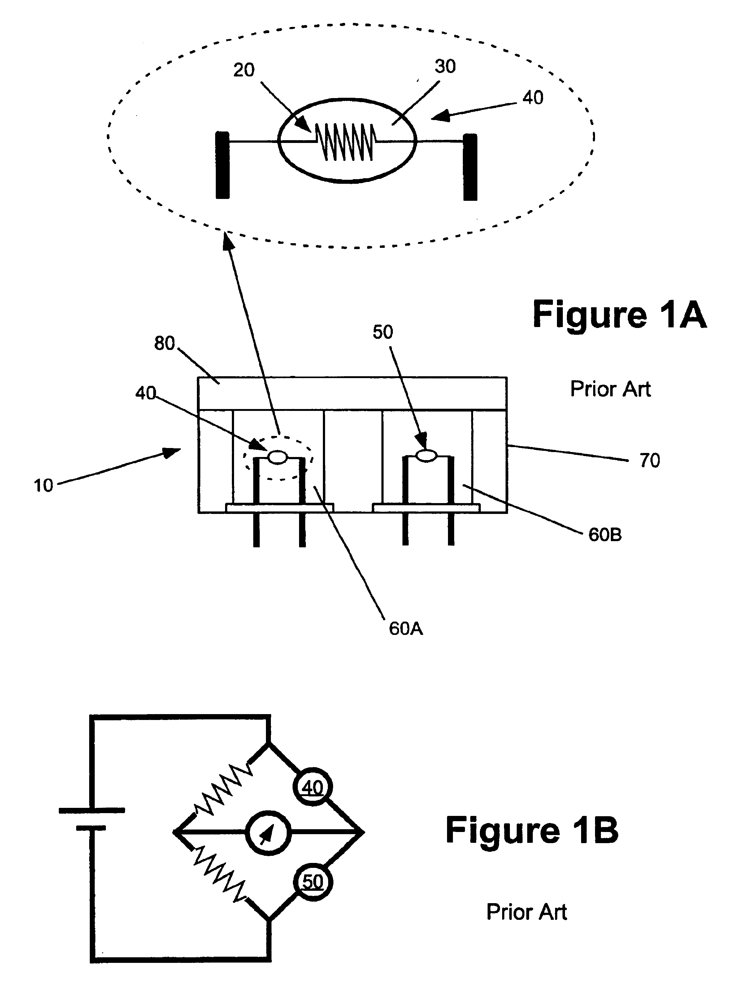
Bead 30 will react to phenomena other than catalytic oxidation that can change its temperature (i.e., anything that changes the energy balance on the bead) and thereby create errors in measurement of combustible gas concentration.
In both conventional sensors and in microsensors, the catalytic element and the compensating element are expensive to produce.
Together, the pair typically accounts for well over half of the cost of the sensor's manufacture.

Method used


Image

  • Catalytic sensor
  • Catalytic sensor
  • Catalytic sensor

Examples


Embodiment Construction

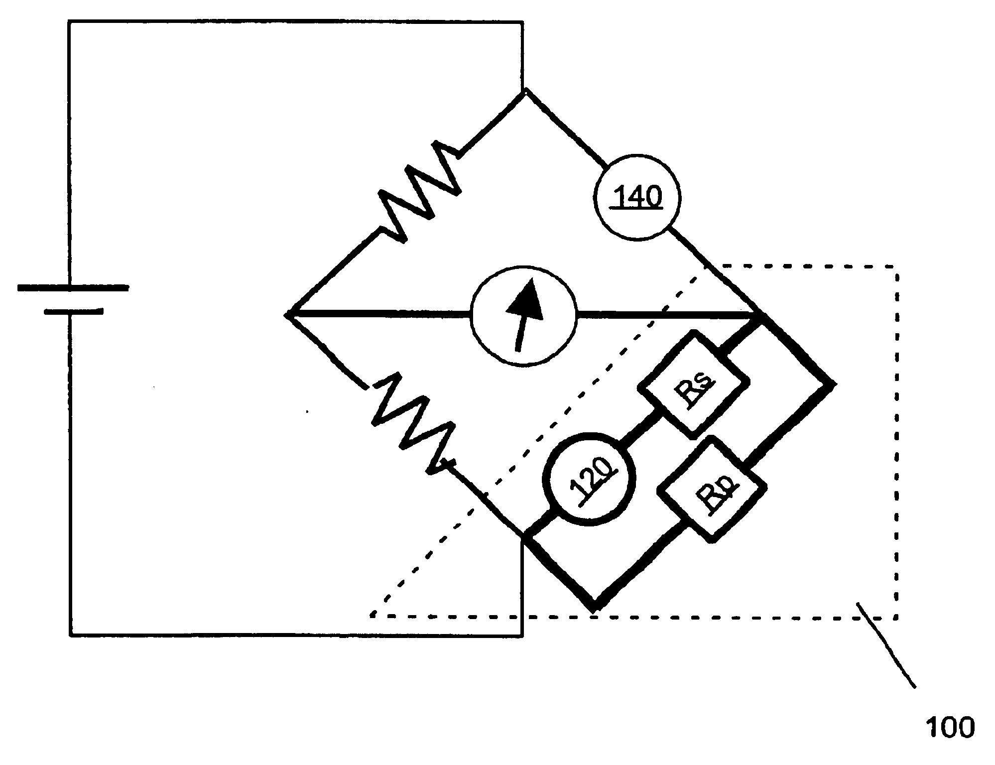
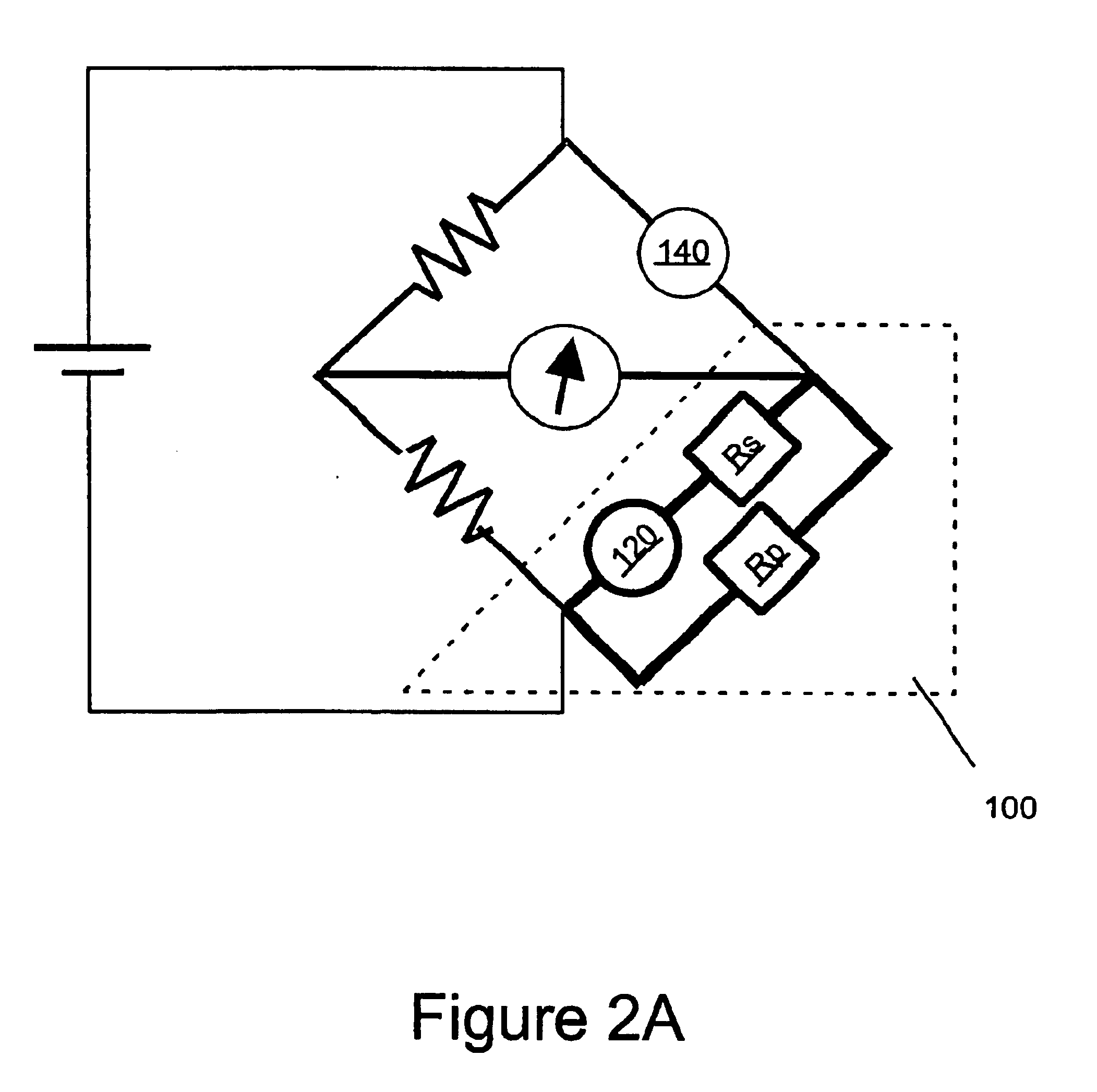
[0027]In the combustible gas sensors of the present invention, expensive compensating elements are eliminated. In several embodiments, such compensating elements are replaced with an inexpensive thermistor network. In general, a thermistor is an inexpensive, commercially available resistor made of materials having resistance that vary rapidly and predictably with temperature. The resistance of a thermistor may either increase or decrease as temperature increase. In the present invention, a thermistor is used to provide the ambient temperature compensating function of a conventional compensating element. As discussed in greater detail below, for catalytic elements of limited geometric or external surface area, accurate measurements of analyte gas concentration can be made while compensating only for ambient temperature changes.

[0028]In the case of a thermistor network, the configuration of the measurement circuitry of the present invention depends upon the direction (that is, directl...


PUM


Abstract

A combustible gas sensor includes an active element in electrical connection with a measurement circuit. The measurement circuit includes a thermistor network to compensate for the effect of changes in ambient temperature to the resistance of the active element. Another combustible gas sensor includes an active element having a geometric surface area no greater than approximately 0.5 mm2 in electrical connection with a measurement circuit. The measurement circuit includes a compensator that compensates for the effect of changes in ambient temperature to the resistance of the active element without compensating for heat lost by thermal conduction from the active element. A method of sensing gas including the steps of: (i) providing a catalytic active element having a geometric surface area sufficiently small such that the effect upon the output of the active element of heat lost from the active element by thermal conduction is relatively small, and (ii) compensating for only the effect of changes in ambient temperature upon the output of the active element.

Description

[0001]This is a continuation of application Ser. No. 09 / 698,740, filed Oct. 27, 2000, now U.S. Pat. No. 6,663,834.FIELD OF THE INVENTION[0002]The present invention relates to catalytic sensors, and, particularly, to catalytic sensors in which a conventional compensating element is eliminated.BACKGROUND OF THE INVENTION[0003]Catalytic or combustible (flammable) gas sensors have been in use for many years to, for example, prevent accidents caused by the explosion of combustible or flammable gases. In general, combustible gas sensors operate by catalytic oxidation of combustible gases. As illustrated in FIG. 1A, a conventional combustible gas sensor 10 typically includes a platinum element or coil 20 encased in a refractory (for example, alumina) bead 30, which is impregnated with a catalyst (for example, palladium or platinum) to form an active pelement 40 or pellistor. A detailed discussion of pelements and catalytic combustible gas sensors which include such pelements is found in Mo...

Claims


Application Information

Patent Timeline
IPC IPC(8): G01N27/14G01N27/16
CPCG01N27/16
Inventor MILLER, JAMES B.HORT, CELESTESCHEFFLER, TOWNER B.
Owner MINE SAFETY APPLIANCES CO
Learn More