Object presence detection method and device

a detection method and object technology, applied in the direction of optical radiation measurement, electric devices, devices using optical means, etc., can solve the problems of not cooperating actively and expensive systems, and achieve the effects of low consumption rate, simple communication, and small siz

Inactive Publication Date: 2005-06-28
FICOSA NORTH AMERICA
View PDF10 Cites 18 Cited by
  • Summary
  • Abstract
  • Description
  • Claims
  • Application Information

AI Technical Summary

Benefits of technology

[0005]In fact, a detection device of this type captures the blind spot image and analyzes it, informing the driver of the result of the analysis. This affords a number of advantages: the driver is now shown the blind spot image, whereby it is not necessary to have space in the compartment for a screen, the driver is additionally provided with information of “greater value” in the sense that the detection device has already effected an analysis and the driver or user is provided with the result of the analysis. Furthermore, the detection device requires receivers with a smaller number of pixels than required to provide the driver with an image of the blind spot having a minimum quality, whereby the detection device may be equipped with cheaper receivers without any loss of performance.
[0026]Finally it is advantageous to add to the object presence detection device a device for detecting drowsiness of the driver. Preferably the drowsiness detection device shares most of the physical devices with the object presence detection device and emits an alarm signal depending on the relative position of the vehicle fitted with the detection device to the lines marking the lanes on the road surface.

Problems solved by technology

These systems make it possible for the user to see in the blind spots without having to move himself, nevertheless, they have a number of drawbacks: they require image transmission systems having a sufficient quality for the user to perceive a clear picture, which requires working with a high number of pixels, there must be space in the passenger compartment to be able to accommodate the corresponding screen, the system does not process the image but only transmit it, etc.
They are, therefore, expensive systems, which do not cooperate actively in the detection of situations of risk.

Method used


Image

  • Object presence detection method and device
  • Object presence detection method and device
  • Object presence detection method and device

Examples


Embodiment Construction

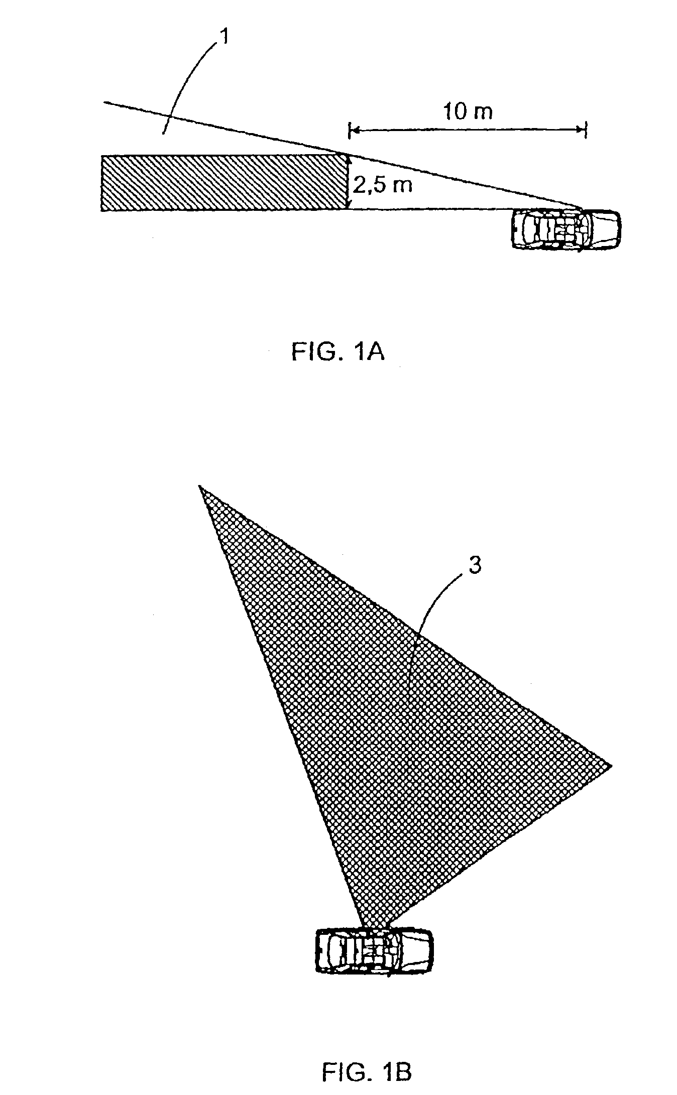
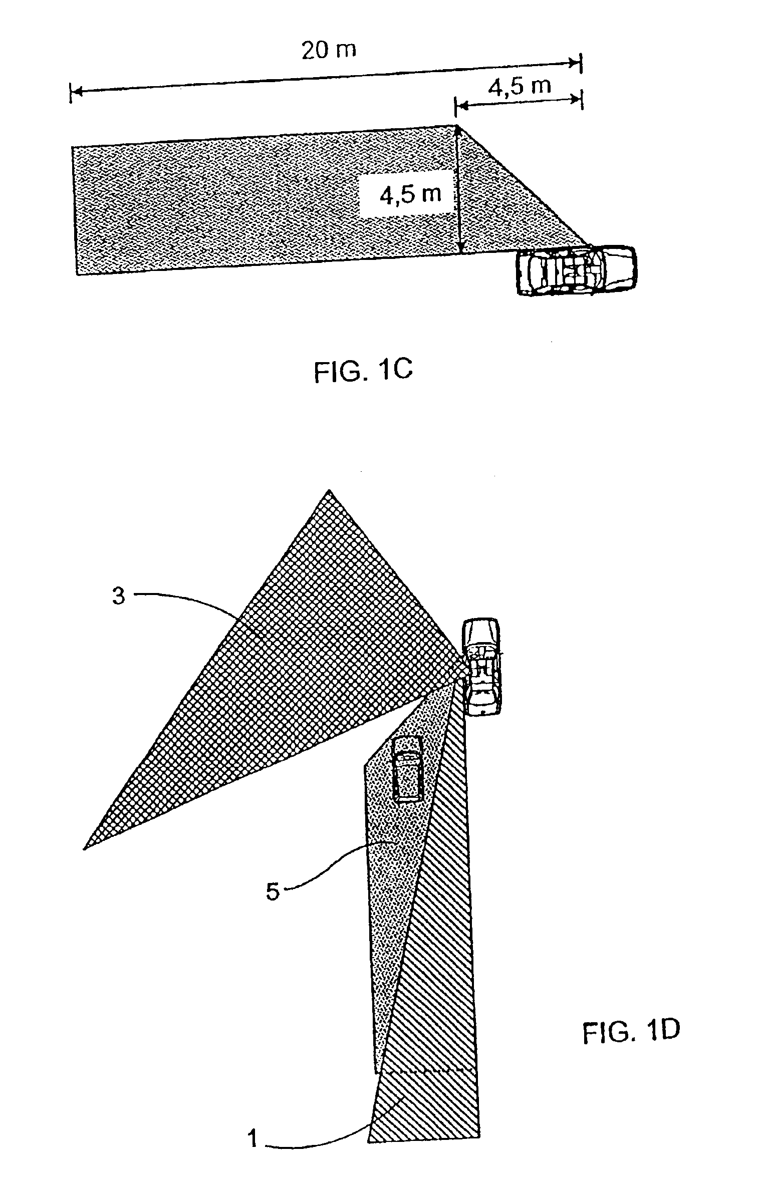
[0034]by way of example, FIGS. 1A to 1D schematically illustrate the areas visible through the left side (driver's side) rear-view mirror 1, the areas visible as a result of the driver's lateral peripheral vision 3, and the blind spots 5. The areas visible through the rear-view mirrors 1 must comply with a number of legal requirements, for example those defined in E.C. Directive 71 / 127 and in the following directives. In particular, as shown in FIG. 1A, the angle of vision should be such that at a distance of 10 m from the rear-view mirror, the width of the area seen should be at least 2.5 m. In FIG. 1A there is to be seen a hatched rectangular area corresponding to the legal requirement, and a triangular area corresponding to what is really seen through a conventional rear-view mirror satisfying the legal requirement.

[0035]It is precisely these blind spots 5 that the detection device of the present invention is intended to cover. The detection device should, furthermore, partially ...


PUM


Abstract

An object presence detection device, of the type mounted to a motor vehicle having at least one blind spot, where the detection device is for detecting an object situated in the blind spot, comprises: a receiver for detecting electromagnetic waves, comprising a focussing device, and a light detector converting said received electromagnetic waves into electrical signals; an electronic circuit converting the electrical signals into digitized signals; a logic circuit analyzing the digitized signals to analyze the presence of objects in the blind spot which are moving relative to the vehicle, and emitting variable output signals depending on the result of the analysis; indicator members activated by the output signals, suitable to be perceived by the driver.

Description

FIELD OF THE INVENTION[0001]The invention relates to an object presence detection method and to a device to put said method into practice, the device being of the type mounted to a motor vehicle having at least one blind spot, where the detection device is for detecting an object situated in the blind spot.BACKGROUND OF THE INVENTION[0002]Conventional motor vehicles are usually provided with rear view mirrors, generally one internal mirror and one or two external mirrors, which allow the user or driver to see behind without the user having to turn his or her head around. Nevertheless, in spite of having a plurality of mirrors there are usually areas, known as blind spots, which are not covered by said mirrors.[0003]There is known the use of systems, which capture an image oriented towards a blind spot by means of a CCD camera and show it to the user on a screen located in the vehicle passenger compartment. These systems make it possible for the user to see in the blind spots without...

Claims


Application Information

Patent Timeline
Patent Type & Authority Patents(United States)
IPC IPC(8): G06T7/20G08G1/16G01S11/00G01S11/12B60R1/00G01B11/24G01P3/36G01V8/10G08B21/00H04N7/18
CPCG06K9/00805G08G1/167G06T7/20G01S11/12G06V20/58
Inventor SARTORI, ALVISETECCHIOLLI, GIAMPIETROCRESPI, BRUNOTARRAGO PUJOL, JOSE MARIADAURA LUNA, FRANCESCBANDE MARTINEZ, DANIEL
Owner FICOSA NORTH AMERICA
Why Eureka
Try Eureka