Metal detector employing static discrimination

a metal detector and static discrimination technology, applied in the field of metal detectors, can solve the problems of significant error introduced by rotation, severe compromise of method performance, and other attempts at dual frequency discrimination have not been successful, so as to improve the discrimination between metal objects and ground.

Inactive Publication Date: 2005-06-28
GARRETT ELECTRONICS
View PDF33 Cites 33 Cited by
  • Summary
  • Abstract
  • Description
  • Claims
  • Application Information

AI Technical Summary

Benefits of technology

[0018]Preferably, the method and apparatus provide for discriminating between the metal object and ground. The ground is interrogated with a third sinusoidal frequency component at the first frequency and a fourth sinusoidal frequency component at the second frequency. Third and fourth response frequency components corresponding to the third and fourth sinusoidal frequency components are determined. The first and second response frequency components are adjusted with information obtained from the third and fourth response frequency components so as to cancel the effect of the ground.
[0022]It is another object of the present invention to provide a metal detector providing improved discrimination between metal objects and ground.
[0023]It is another object of the present invention to provide a metal detector providing improved discrimination between ferrous and non-ferrous metal objects.

Problems solved by technology

It is a problem in the metal detector art to eliminate all the ferrous mineral signals in the target volume of ground while retaining sufficient information to identify the metal objects.
For either ferritic or conductive ground, it is necessary to minimize or eliminate the effect of the ground on the received signals, and this is a problem in the art.
Other attempts at dual frequency discrimination have not been successful.
However, these signals are not free of the effects of ground which severely compromises the performance of the method.
However, a significant error is introduced by the rotation.
In addition, it is a problem in all of these methods that ferrous and non-ferrous metals can be confused with one another, and it is often desired to be able to discern that a metal object is ferrous so that the user can decide to expend no further effort to uncover the object.
Motion discrimination has the obvious disadvantage that it is demanding of the user in terms of both effort and skill.
It may also result in ambiguities where there are multiple metal objects in the target volume.

Method used


Image

  • Metal detector employing static discrimination
  • Metal detector employing static discrimination
  • Metal detector employing static discrimination

Examples


Embodiment Construction

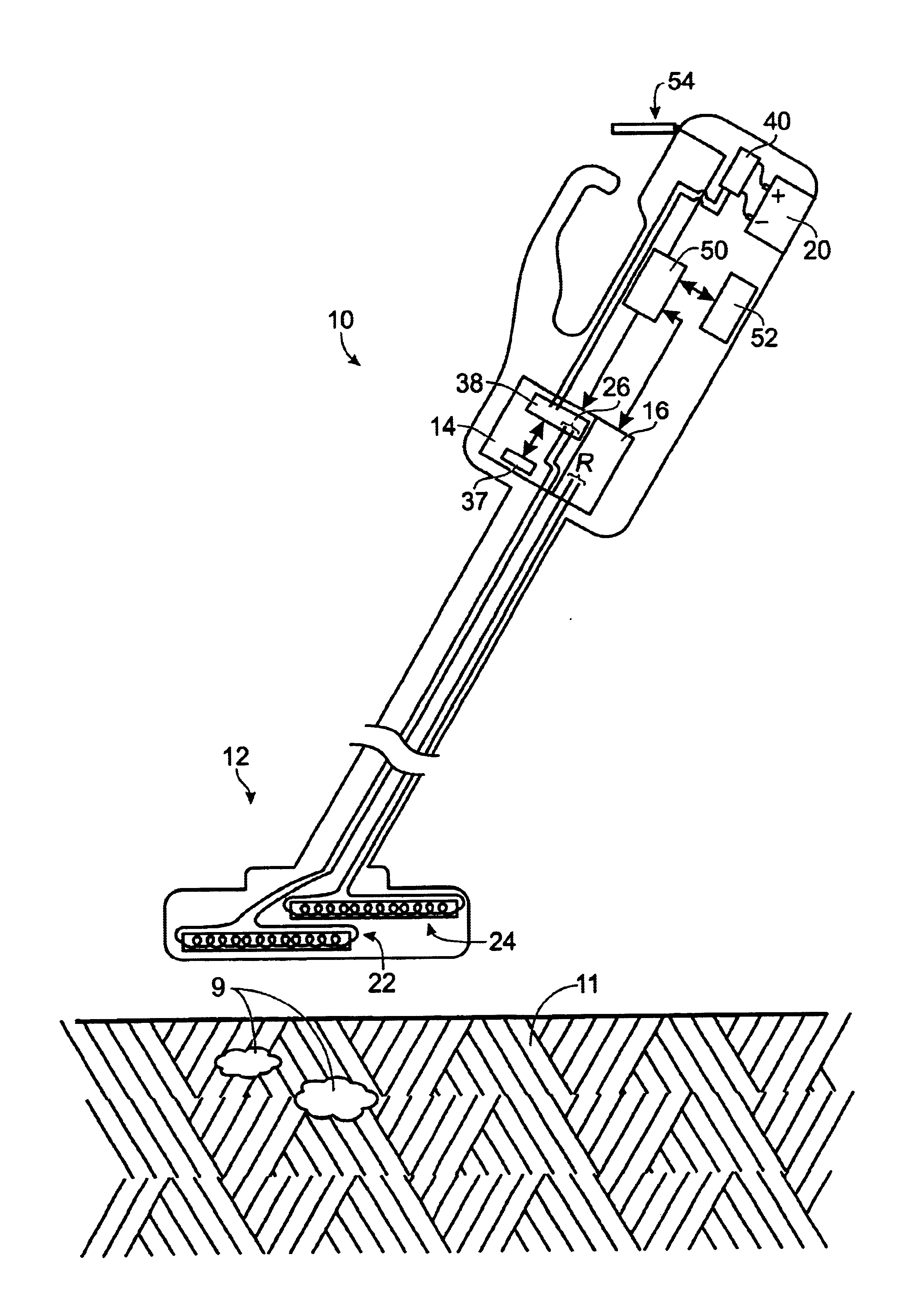
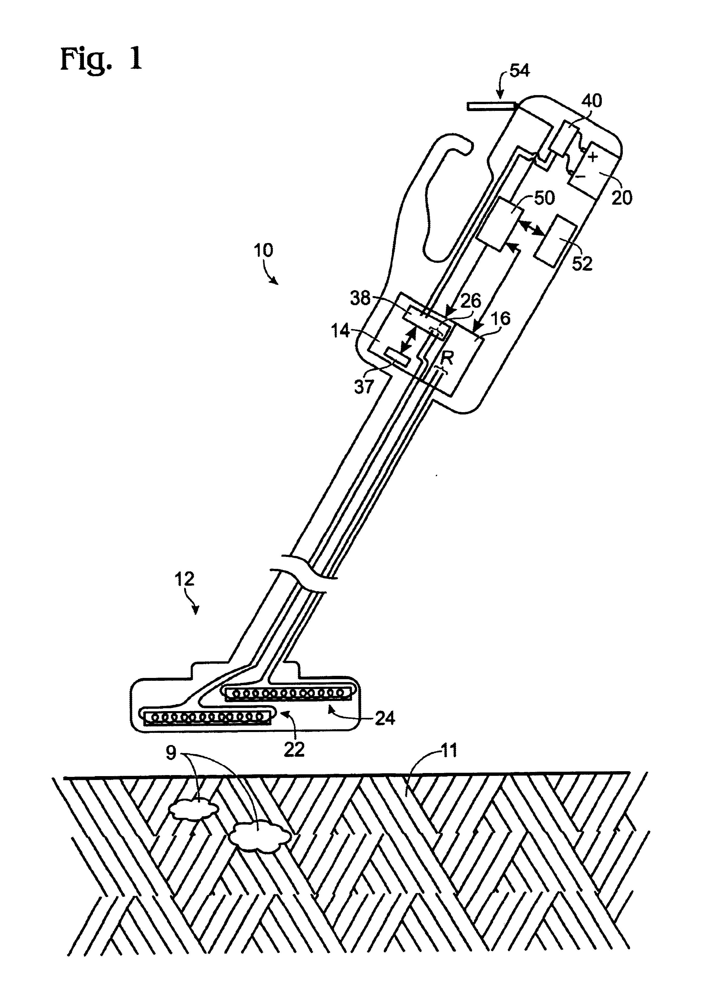
[0031]Referring to FIG. 1, a metal detector 10 is shown. The metal detector 10 is particularly adapted for hand-held use, such as by hobbyists, however, this is not essential to the context of the present invention. The detector is used to search for metal objects 9 in a target volume 11 that is typically ground but may be any volume. Since the detector is typically used outdoors to search for metal objects away from independent sources of power, the detector typically incorporates a battery 20 to power the detector, though the detector 10 may be used with any power source.

[0032]The metal detector 10 includes an interrogating portion, a receiving portion, and a processing portion. The interrogating and receiving portion share a search head 12. The interrogating portion comprises a signal generator 14 and the receiving portion comprises a sampling circuit 16. The search head is maintained in close proximity with the ground 11. The signal generator 14 generates interrogating signals f...


PUM

PropertyMeasurementUnit
frequencyaaaaaaaaaa
frequenciesaaaaaaaaaa
frequencyaaaaaaaaaa

Abstract

A metal detector employing static discrimination. Within the scope of the invention is a two-frequency method and apparatus for discriminating between metal objects and ground. Also within the scope of the invention is a three-frequency method and apparatus for discriminating between ferrous and non-ferrous metal objects. The methods and apparatus do not require movement of the search head of the metal detector.

Description

REFERENCE TO RELATED APPLICATIONS[0001]This is a continuation-in-part of U.S. Ser. No. 10 / 074,349, filed Feb. 11, 2002.FIELD OF THE INVENTION[0002]The present invention relates generally to a metal detector employing static discrimination between metal objects and ground, and between ferrous and non-ferrous metal objects.BACKGROUND OF THE INVENTION[0003]Metal detectors are popularly used by hobbyists and collectors to search for buried or otherwise hidden metal objects of value or particular interest, such as coins, jewelry, and artifacts of historical significance. The metal detectors typically employ a transmit coil through which current flows, the current establishing time-varying magnetic fields that induce eddy currents in metal objects, and interact with any magnetic permeability of the metal object. These effects are detected in a receive coil, and are used to identify the metal objects.[0004]In addition to metal objects of interest, the ground itself typically contains metal...

Claims


Application Information

Patent Timeline
Patent Type & Authority Patents(United States)
IPC IPC(8): G01V3/10
CPCG01V3/104
Inventor ROWAN, MARK D.
Owner GARRETT ELECTRONICS
Why Eureka
Try Eureka