Optical compensator and liquid crystal display I

a liquid crystal display and optical compensation technology, applied in the direction of instruments, polarising elements, thin material handling, etc., can solve the problems of severe drawbacks in mass production, achieve the effect of suppressing grey scale inversion, improving contrast at large viewing angles, and superior performance of liquid crystal display compensation

Inactive Publication Date: 2005-06-28
MERCK PATENT GMBH
View PDF20 Cites 28 Cited by
  • Summary
  • Abstract
  • Description
  • Claims
  • Application Information

AI Technical Summary

Benefits of technology

[0049]The inventors of the present invention have found that the above drawbacks can be overcome, and an optical compensator with superior performance for compensation of the optical properties of liquid crystal displays can be obtained by using a combination of at least two ORFs, one of said at least two ORFs being either a tilted or a splayed O plate, and the other of said at least two ORFs being a twisted A plate.
[0050]When using an optical compensator according to the present invention in an LCD, the contrast at large viewing angles and the grey level representation of the display are considerably improved, and grey scale inversion is suppressed. In case of coloured displays the colour stability is considerably improved and changes of the colour gamut are suppressed. Furthermore, a compensator according to the present invention is particularly suitable for mass production for the following reason.
[0052]Therefore, when using a combination of an O plate and a twisted A plate according to the present invention, instead of a combination of an O plate and a planar A plate as suggested in WO 97 / 44703, the requirement of crossed principal optical axes of the two ORFs and the above discussed problems of mass production of the ORFs thereby incurred are easily circumvented.
[0054]Furthermore, the inventors of the present invention have found that it is possible to provide an optical compensator with particularly improved properties by using an O plate in combination with a highly twisted A plate. The term ‘highly twisted’ in this connection means a twisted A plate as defined above, wherein the twist angle φ is at least 360°.

Problems solved by technology

However, the embodiment of the compensators as disclosed in WO97 / 44703 implies severe drawbacks for its mass production.

Method used


Image

  • Optical compensator and liquid crystal display I
  • Optical compensator and liquid crystal display I
  • Optical compensator and liquid crystal display I

Examples


example 1

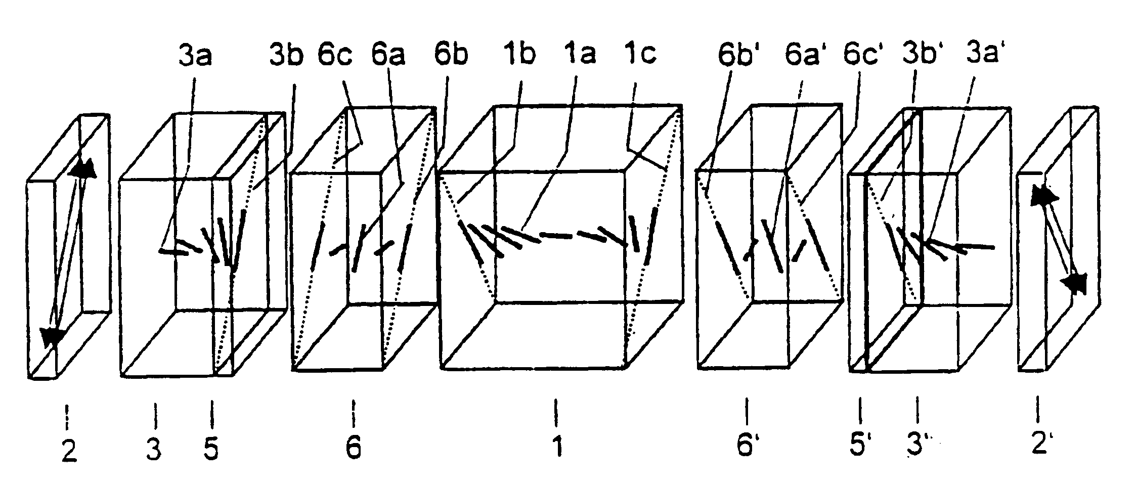
[0216]A compensated TN-LCD device according to the present invention as depicted in FIG. 3 comprises a TN cell 2, a pair of linear polarizers 2,2′, two splayed O plates 3,3′ and two twisted A plates 6,6′, each ORF being provided on a substrate 5,5′, wherein the TN cell 1 and the linear polarizers 2,2′ are as defined in comparison example A.

[0217]The splayed O plates 3,3′ are as defined in comparison example B, except for the film thickness d being 3.0 μm.

[0218]The substrates 5,5′ are negatively birefringent TAC films with the following refractive indices

[0219]

nx1.48158ny1.48153nz1.48090

wherein the x and y are directions parallel to the film plane and z is the direction perpendicular to the film plane.

[0220]The parameters of the twisted A plates 6,6′ are as follows

[0221]

ne1.610no1.495d″3.0 μmpφ>5400°

[0222]FIG. 7a shows the isocontrast plot of the display, FIG. 7b and FIG. 7c show the grey levels (transmission versus viewing angle) in horizontal and vertical directions respectively. I...

example 2

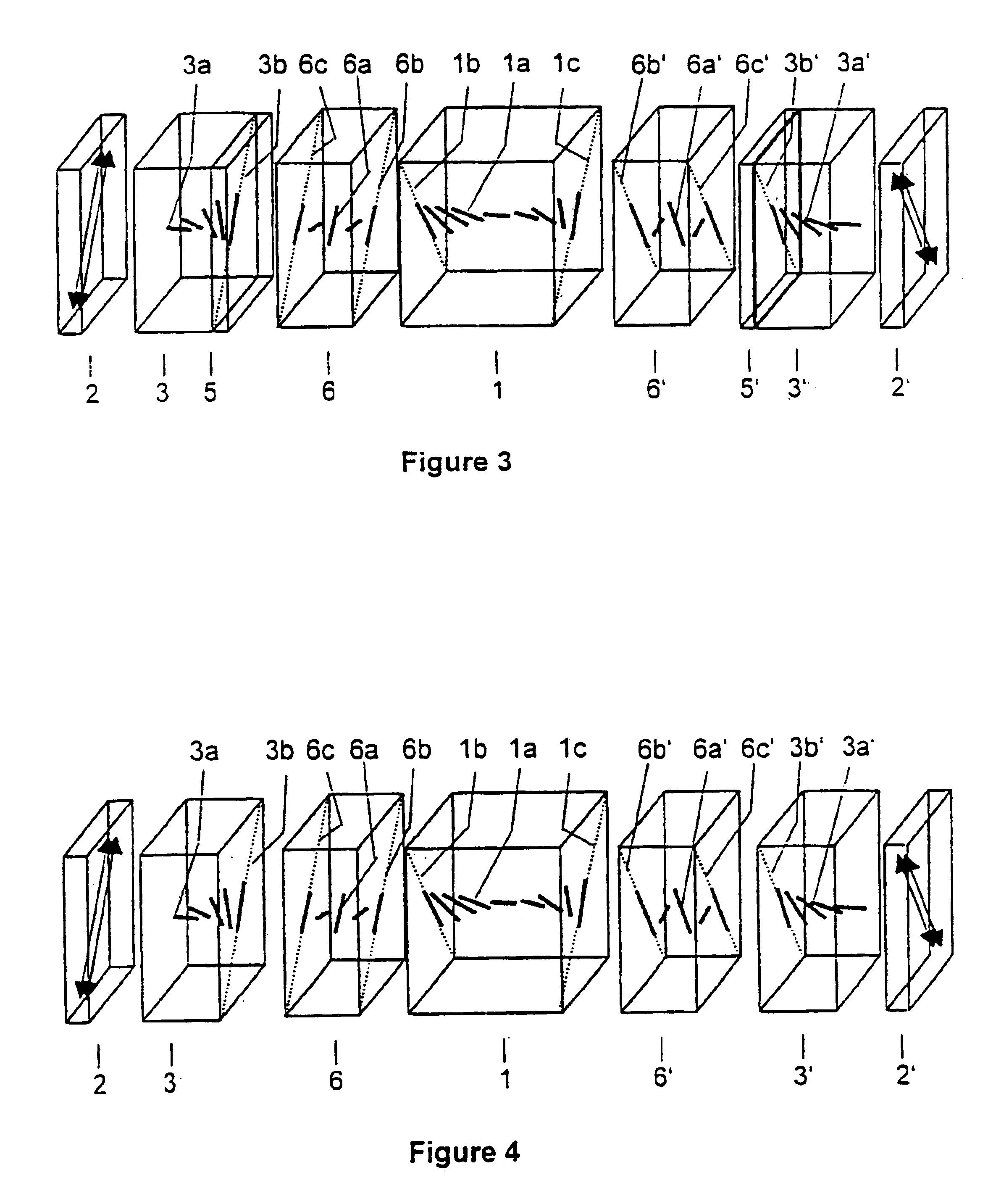
[0223]A compensated TN-LCD device according to the present invention as depicted in FIG. 4 a TN cell 2, a pair of linear polarizers 2,2′, two splayed O plates 3,3′ and two twisted A plates 6,6′, wherein the TN cell 1 and linear polarizers 2,2′ are as defined in comparison example A.

[0224]The splayed O plates 3,3′ are as defined in comparison example B, except for the film thickness d being 3.0 μm. The twisted A plates 6,6′ are as defined in example 1, except for the film thickness d being 40 μm and the twist angle φ being >7200°.

[0225]FIG. 8a shows the isocontrast plot of the display, FIG. 8b and FIG. 8c show the grey levels (transmission versus viewing angle) in horizontal and vertical directions respectively. It is obvious that, compared to the compensated display according to prior art of comparison example B, the viewing angle is significantly enlarged (see FIG. 8a), and the grey levels are further improved, both in horizontal and vertical direction.

example 3

[0226]The following polymerizable mixture was formulated

[0227]

Compound (1)7.5%Compound (2)10.5%Compound (3)21.5%Compound (4)49.5%Compound (5)6.5%Irgacure 1076 ®4.0%Fluorad FC1710.5%(1) (2) (3) (4) (5)

[0228]Compounds (1) and (3) can be prepared according to or in analogy to the methods described in D. J. Broer et al., Makromol. Chem. 190, 3201-3215 (1989). The direactive compounds (2) and (4) can be prepared as described in WO 93 / 22397. The preparation of compound (4) is described in WO 98 / 00428. Irgacure 907 is a commercially available photoinitiator (from Ciba AG, Basel, Switzerland). Fluorad FC 171 is a commercially available non-ionic fluorocarbon surfactant (from 3M Corp.).

[0229]Samples of the above mixture were coated from a solution in toluene (Concentration range 15-30% by weight) onto a TAC substrate of 80 μm thickness, which had been previously rubbed to induce planar alignment on the substrate surface, to give coatings of different thickness. After coating the samples wer...


PUM

PropertyMeasurementUnit
twist angleaaaaaaaaaa
tilt angleaaaaaaaaaa
twist angleaaaaaaaaaa

Abstract

The invention relates to an optical compensator for liquid crystal displays comprising: at least one O plate retarder (3, 3′), and at least one twisted A plate retarder (6, 6′) with a twist angle φ of more than 90°, and further relates to a liquid crystal display comprising such a compensator, a liquid crystal cell (1) and polarizers (2, 2′).

Description

FIELD OF THE INVENTION[0001]The invention relates to an optical compensator for liquid crystal displays and to a liquid crystal display comprising such a compensator.BACKGROUND AND PRIOR ART[0002]Optical compensators are used to improve the optical properties of liquid crystal displays (LCD), such as the contrast ratio and the grey scale representation at large viewing angles. For example in uncompensated displays of the TN or STN type at large viewing angles often a change of the grey levels and even grey scale inversion, as well as a loss of contrast and undesired changes of the colour gamut are observed.[0003]An overview of the LCD technology and the principles and methods of optical compensation of LCDs is given in U.S. Pat. No. 5,619,352, the entire disclosure of which is incorporated into this application by way of reference.[0004]As described in U.S. Pat. No. 5,619,352, to improve the contrast of a display at wide viewing angles a negatively birefringent C-plate compensator c...

Claims


Application Information

Patent Timeline
Patent Type & Authority Patents(United States)
IPC IPC(8): G02B5/30G02F1/13G02F1/00G02F1/13363
CPCG02B5/3016G02B5/3083G02F1/133636Y10T428/10G02F2413/105Y10T428/1036G02F2413/10C09K2323/00C09K2323/03G02F1/13363
Inventor COATES, DAVIDPARRI, OWAIN LLYRVERRALL, MARKLE MASURIER, PETER
Owner MERCK PATENT GMBH
Why Eureka
Try Eureka