Memory system with dynamic timing correction

a memory system and dynamic timing technology, applied in the field of memory systems and memory devices, can solve the problems of preventing the memory system from operating at its optimal rate, data arriving later, propagation delay between,

Inactive Publication Date: 2005-06-28
ROUND ROCK RES LLC
View PDF252 Cites 96 Cited by
  • Summary
  • Abstract
  • Description
  • Claims
  • Application Information

AI Technical Summary

Benefits of technology

[0010]The use of a plurality of phase detectors driven by taps of a delay-locked loop allows the echo clock signal to be phase compared to the master clock signal in real time. Thus, the memory controller can dynamically adjust timing of the memory devices to accommodate drift in routing delays of the memory system.

Problems solved by technology

One problem that often occurs in such system arises from differences in propagation times of signals between a memory controller and memory devices controlled by the memory controller.
Such timing differences may prevent the memory system from operating at its optimum rate.
If one of the memory devices outputs data at the specified clock edge propagation delays from the memory device to the memory controller may cause the data to arrive later than the specified clock edge.
One problem with such an approach is that propagation delays between the memory device and memory controller will depend upon the effective distance between the memory controller and the memory device, which depends upon the routing of signal lines connecting the memory controller to the memory device.
The overall speed of the memory system is limited correspondingly.

Method used


Image

  • Memory system with dynamic timing correction
  • Memory system with dynamic timing correction
  • Memory system with dynamic timing correction

Examples


Embodiment Construction

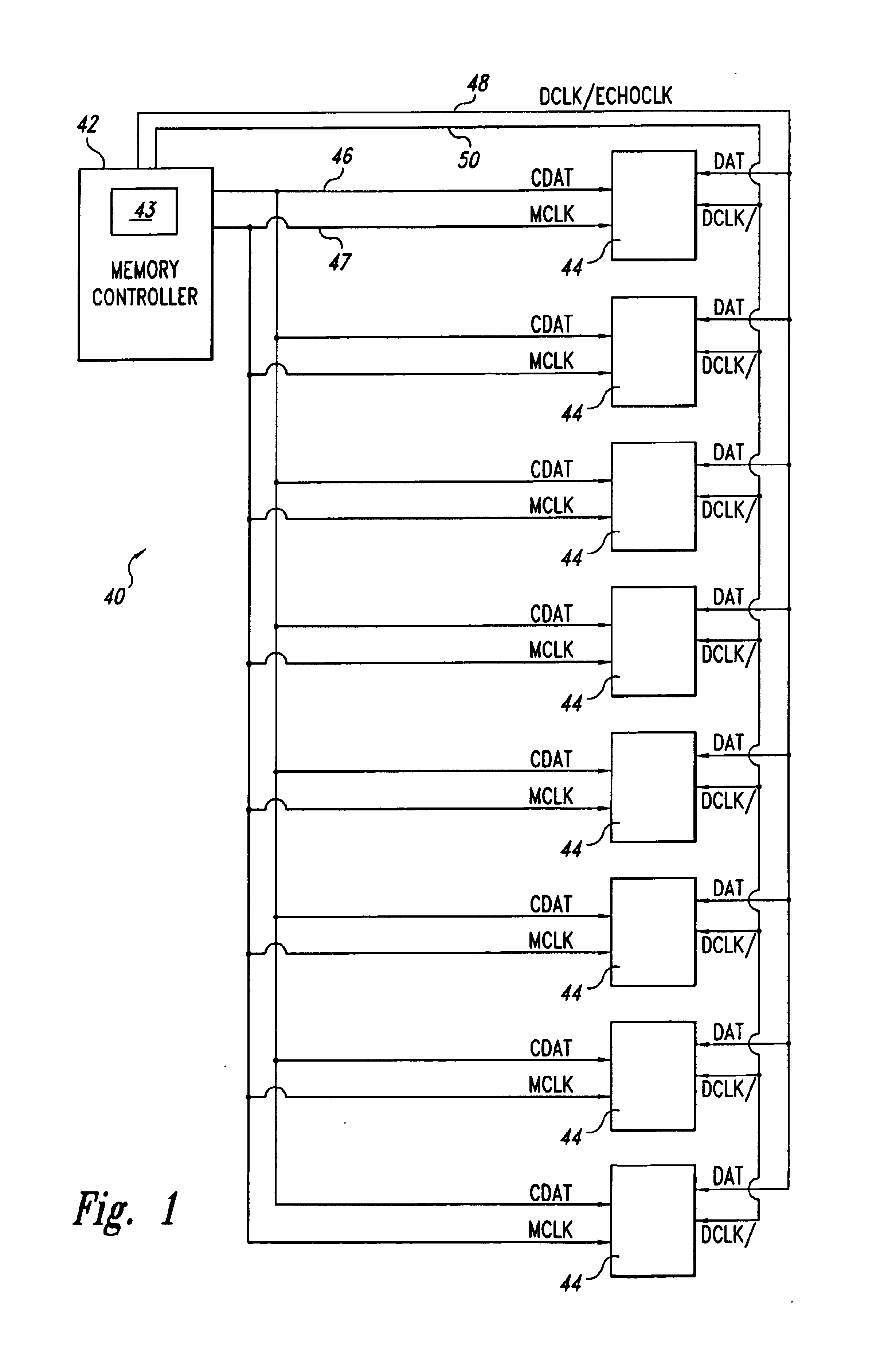
[0017]As shown in FIG. 1, a memory system 40 includes a memory controller 42 that controls eight memory devices 44 as directed by a logic control circuit 43. The memory devices 44 and memory controller 42 operate according to a packet protocol. According to the packet protocol, the controller 42 generates a control data packet containing control data CDAT for reading to or writing from one of the memory devices 44 or for initiating a memory event, such as reset or autorefresh. Among the control data CDAT, the data packet includes fields identifying the memory device 44 to which the packet is directed, fields containing command data, and fields containing addressing information, such as row, column, bank, or register addresses. The memory controller 42 transmits the control data packet to all of the memory devices 44 on a control data bus 46 that is coupled to control data inputs of all of the memory devices 44.

[0018]In addition to the control data packets, the memory controller 42 a...


PUM


Abstract

A memory system includes a memory controller and a bank of memory devices. The memory controller controls the memory devices through packets of control data and a master clock signal. Each of the memory devices includes an adjustable output timing vernier that can be adjusted in response to commands from the memory controller. The vernier output controls timing of output data relative to the master clock signal. As each memory device transmits data to the memory controller, the memory device also transmits an echo clock signal coincident with the data. The memory controller receives the echo clock signal and compares the echo clock signal to the master clock signal to identify shifts in timing of the echo clock signal. If the echo clock signal shifts by more than one vernier increment from the master clock signal, the master controller issues a command to the memory device to adjust the output vernier to correct the timing drift of the echo clock signal. By correcting the timing drift of the echo clock signal, the memory controller also corrects timing drift of the output data, thereby assuring that the data arrive at the memory controller coincident with edges of the master clock signal.

Description

TECHNICAL FIELD[0001]The present invention relates to memory systems and memory devices, and more particularly, to dynamic timing correction in memory systems and memory devices.BACKGROUND OF THE INVENTION[0002]Timing of operations in synchronous memory systems must tightly controlled if the memory system is to operate at optimum rates. Typically, timing of operations in synchronous systems is controlled by a memory controller operating in synchronization with edges of the master clock signal.[0003]One problem that often occurs in such system arises from differences in propagation times of signals between a memory controller and memory devices controlled by the memory controller. Such timing differences may prevent the memory system from operating at its optimum rate. For example, the memory controller typically accepts new data from a memory device at leading clock edges (i.e., transitions of the master clock signal from low to high). If one of the memory devices outputs data at th...

Claims


Application Information

Patent Timeline
Patent Type & Authority Patents(United States)
IPC IPC(8): G11C29/00G11C7/10G11C7/22
CPCG11C7/1051G11C7/1063G11C7/1066G11C7/222G11C29/028G11C29/50012G11C7/22G11C2207/2254
Inventor KEETH, BRENT
Owner ROUND ROCK RES LLC
Why Eureka
Try Eureka