Cylinder driving system and energy regenerating method thereof

a technology of cylinder driving system and energy regenerating method, which is applied in the direction of piston pump, fluid coupling, servomotor, etc., can solve the problems of increasing manufacturing costs, increasing time required for piping work, and unable to efficiently work the hydraulic cylinder. achieve the effect of increasing energy efficiency

Inactive Publication Date: 2005-07-05
KOMATSU LTD
View PDF12 Cites 62 Cited by
  • Summary
  • Abstract
  • Description
  • Claims
  • Application Information

AI Technical Summary

Benefits of technology

[0012]According to this method, a closed circuit of a hydraulic cylinder driving system can be configured by one hydraulic pump, and the regenerated energy during the regenerative braking of the hydraulic pump can be recovered by the electric motor, whereby energy efficiency can be increased.

Problems solved by technology

Accordingly, the time required for piping work is greater, and moreover manufacturing costs increase.
Hence, there is a disadvantage that energy loss of the pressure oil in the control valve 71 is large, whereby efficient work by the hydraulic cylinder becomes impossible.

Method used


Image

  • Cylinder driving system and energy regenerating method thereof
  • Cylinder driving system and energy regenerating method thereof
  • Cylinder driving system and energy regenerating method thereof

Examples


first embodiment

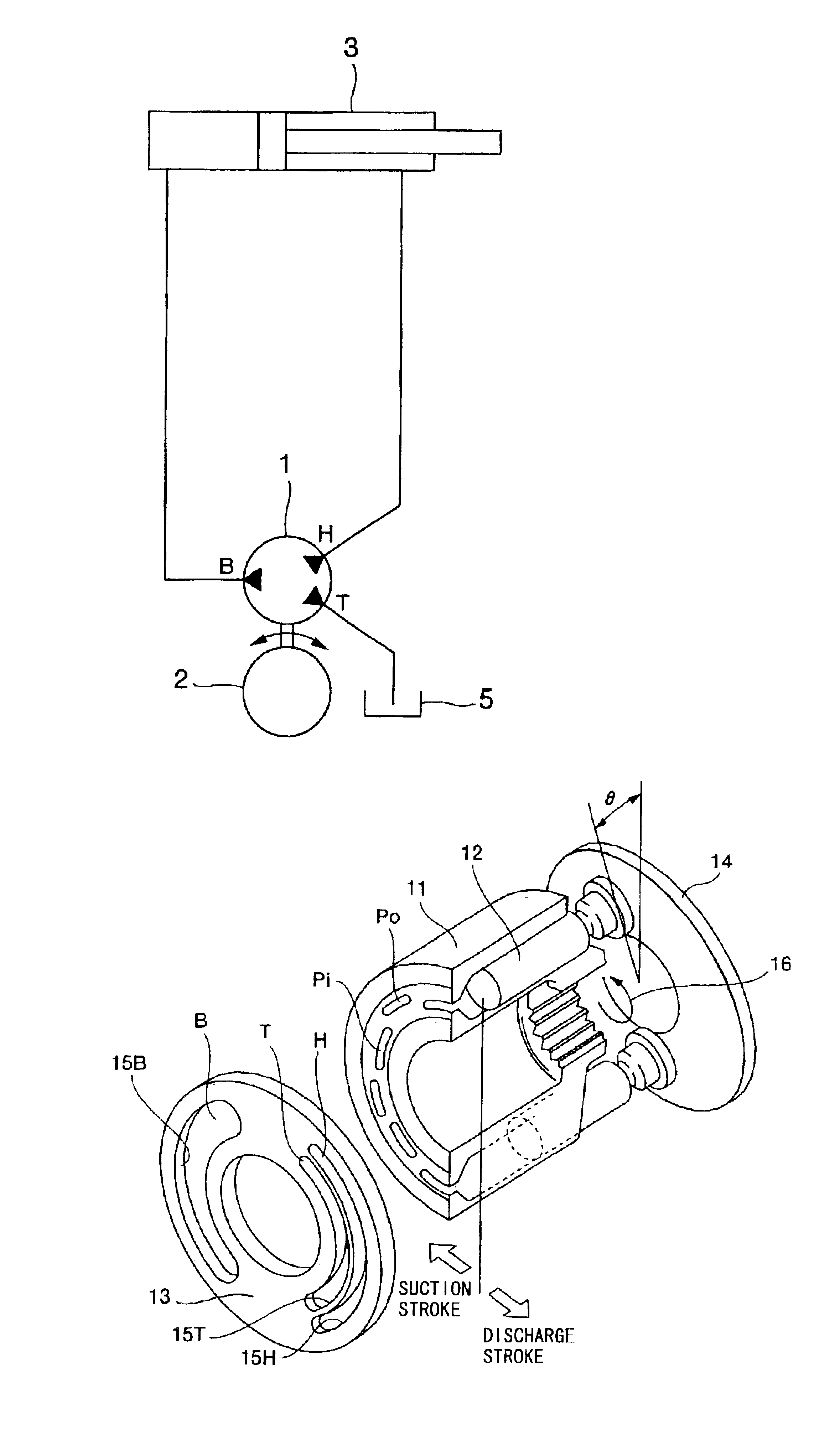
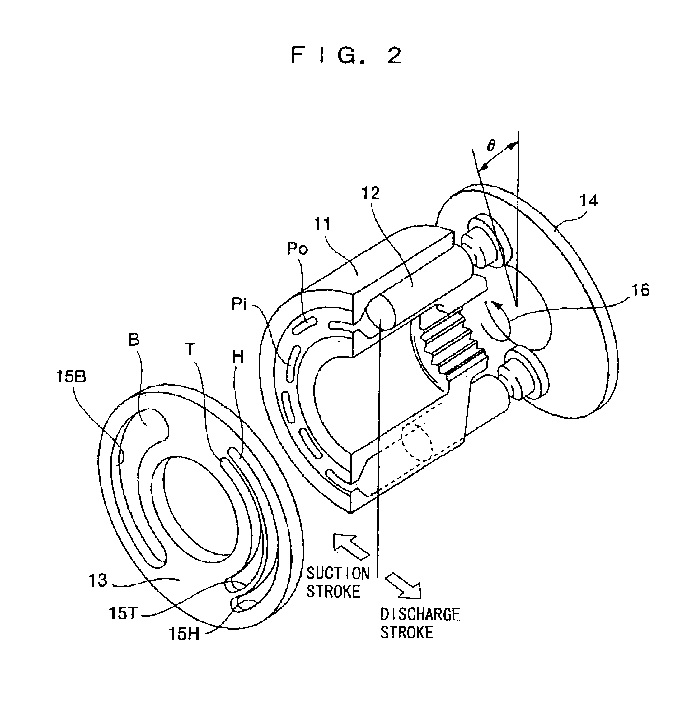
[0049]The respective cylinder holes 38 formed in the cylinder block 35 correspond to the port H and the port T (See FIG. 1) as shown in FIG. 8, and in this example, the same cylinder configuration as that in the first embodiment shown in FIG. 3 is used. As shown in FIG. 6 and FIG. 7, in bottom portions of the respective cylinder holes 38 corresponding to the port H and the port T, the outside ports Po and the inside ports Pi, which allow the cylinder holes 38 and a bottom surface of the cylinder block 35 to communicate with each other, are formed. In the valve plate 37, with a shaft center as a center, an arcuate long hole 37B constituting the port B is formed on one side. An arcuate long hole 37H constituting the port H on the outside of the other side and an arcuate long hole 37T constituting the port T on the inside of the other side are formed in parallel with each other in a circumferential direction. The long hole 37B communicates with the outside ports Po and the inside ports...

second embodiment

[0059]As a result, the following effect is obtained in addition to the effects in the Fine adjustment can be made in such a manner that the volumetric efficiency is optionally changed by adjusting the relative angles of the ports H and T of the two plates 37a and 37b constituting the valve plate 37 to thereby obtain the ratio α fitted to the hydraulic cylinder. Accordingly, one and the same hydraulic pump can be used for various types of hydraulic cylinders, whereby the general versatility can increase, and the hydraulic pump can be used in common, leading to reduced inventory management cost and manufacturing cost.

[0060]Next, a fifth embodiment will be explained by means of FIG. 11 and FIG. 12. FIG. 11 is a plan view of a valve plate of a hydraulic pump according to the fifth embodiment, and FIG. 12 is a sectional view taken along the line 12—12 in FIG. 11. The explanation is given with the same bent axis pump as shown in FIG. 6 in the second embodiment as an example of a machine ...


PUM


Abstract

A cylinder driving system capable of reducing the number of hydraulic devices and the amount of energy loss and an energy regenerating method thereof are provided. To this end, the system includes i) a hydraulic cylinder, ii) a hydraulic pump having three suction/discharge ports of a first port for supplying oil to a bottom chamber of the hydraulic cylinder or draining oil from the bottom chamber, a second port for draining oil from a head chamber of the hydraulic cylinder or supplying oil to the head chamber, and a third port for draining oil from a tank or supplying oil to the tank, the suction rate or the discharge rate in the first port being the sum of the respective discharge rates or suction rates in the second port and the third port, and iii) a driving source for driving the hydraulic pump.

Description

TECHNICAL FIELD[0001]The present invention relates to a cylinder driving system and an energy regenerating method thereof.BACKGROUND ART[0002]Hitherto, as methods of controlling the flow rate of a hydraulic cylinder which is frequently used in construction equipment, a working vehicle, industrial machinery, or the like, a method of controlling the rotation speed and rotation direction of a hydraulic pump and a method of controlling the displacement of a bi-directional dischargeable type (bent axis type, swash plate type, or the like) hydraulic pump are known.[0003]An example of prior arts of the aforementioned method of controlling the rotation speed and rotation direction of the hydraulic pump is disclosed in International Publication WO 01 / 88381, and FIG. 13 shows a principal portion of a driving circuit diagram disclosed in said Bulletin. In FIG. 13, two hydraulic pumps 41 and 42 are driven by an electric motor 2. One output port of the first hydraulic pump 41 is connected to a h...

Claims


Application Information

Patent Timeline
Patent Type & Authority Patents(United States)
IPC IPC(8): E02F9/22F15B11/00F15B7/00F15B7/08F15B21/08F15B21/00F15B11/17
CPCE02F9/2217E02F9/2228E02F9/2235F15B7/006F15B7/08F15B11/17F15B21/08F15B2211/20576F15B2211/27F15B2211/30515F15B2211/50518F15B2211/5159F15B2211/55F15B2211/6651F15B2211/7142F15B2211/785F15B2211/214Y02P80/10
Inventor INOUE, HIROAKIKANAYAMA, NOBORUITOW, KOICHIROHIRAKI, HIKOSABUROSAITO, HIDEAKI
Owner KOMATSU LTD
Why Eureka
Try Eureka