Method of securing a shim to a backing plate and subassembly formed thereby

a technology of backing plate and sub-assembly, which is applied in the direction of braking elements, slack adjusters, braking members, etc., can solve the problems of less than desirable construction described in the '244 patent, the adhesive alone is not sufficient to prevent dislodging, and the likelihood of delamination of the shim is reduced

Inactive Publication Date: 2005-07-05
ANSTRO MFG INC
View PDF10 Cites 32 Cited by
  • Summary
  • Abstract
  • Description
  • Claims
  • Application Information

AI Technical Summary

Benefits of technology

[0015]Therefore, it is an object and advantage of the present invention to provide an improved mechanical interlocking attachment for securing a shim to a backing plate in a brake assembly.
[0016]It is a further object and advantage of the present invention to provide an improved methodology of attaching a shim to a backing plate in a brake assembly.
[0017]It is still a further specific object and advantage of the present invention to provide an improved methodology (and resulting assembly) of attaching a shim to a backing plate in a brake assembly that decreases the likelihood of delamination of the shim from the backing plate.
[0018]And it is yet a further object and advantage of the present invention to provide an improved methodology (and resulting assembly) of attaching a shim to a backing plate in a brake assembly that does result in any interference by the pins that assist in securing the shim to the backing plate.
[0019]Yet another object of the present invention is to provide a way to ensure that the shim sits flat on the backing plate during the mounting thereof on the backing plate, and thereafter.

Problems solved by technology

A high pitched and undesired brake squeal noise can be produced during such braking engagement of the pads on the disc, which may be produced by vibration of the subassemblies during braking actuation.
Unfortunately, this frictional contact can cause a torque or twisting force on the shim by the related piston or caliper producing a shearing force in the adhesive of the shim.
Under the extreme conditions of heat and vibration the adhesive by itself is not sufficient to prevent dislodging of the shim from the backing plate during braking.
As such, it can be readily seen that the construction described in the '244 patent is less than desirable.
Secondly, any resulting construction must satisfactorily address the problem of delamination of the shim from the backing plate, which the inventors believe is achieved less than satisfactorily in the cited patents.

Method used


Image

  • Method of securing a shim to a backing plate and subassembly formed thereby
  • Method of securing a shim to a backing plate and subassembly formed thereby
  • Method of securing a shim to a backing plate and subassembly formed thereby

Examples


Embodiment Construction

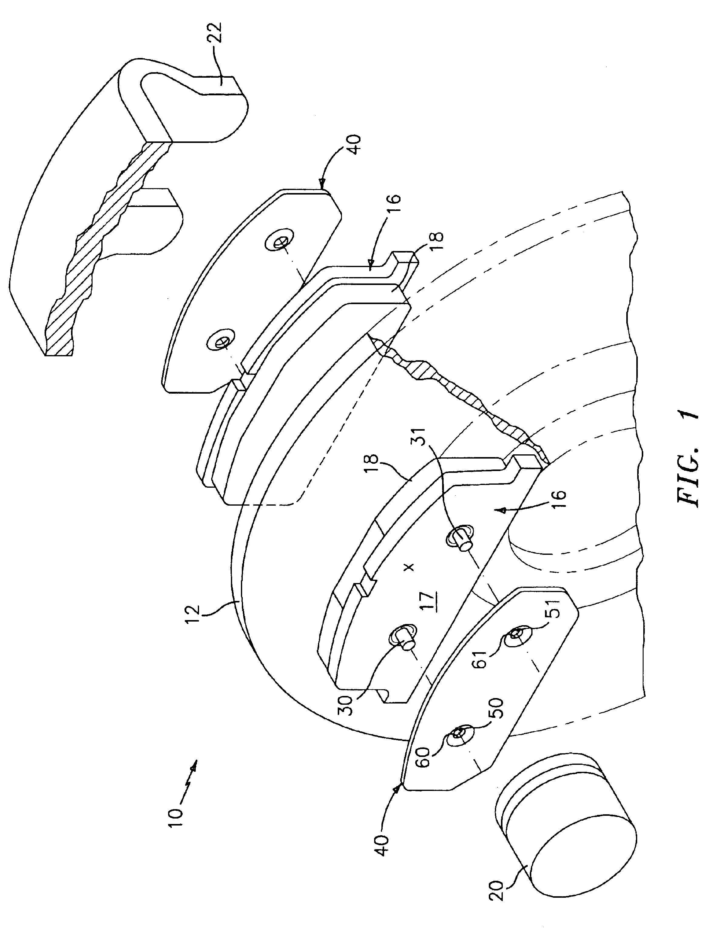
[0030]Reference is very briefly made to FIG. 1 for a general description of an exploded view of a disc-brake assembly, generally indicated at 10. A more detailed description can be found in the aforementioned '684 application, and need not be repeated herein for purposes of brevity and because the general understanding of such a brake assembly is so well known to those skilled in the art.

[0031]By way of general background however, it is well-known that a disc brake assembly, generally indicated at 10, is used to stop a rotatable disc 12 which rotates with the axle of a wheel to be braked. Assembly 10, as defined herein, can be seen to include opposing braking subassemblies, each of which comprising a steel backing plate, generally indicated at 16, and a brake pad 18 mounted on the side of backing plate 16 facing disc 12. The two backing plates 16 may be suspended in a conventional caliper mounting structure by rods (not shown) which extend through backing plates 16, thus permitting ...


PUM


Abstract

A method of securing a shim against a first side surface of a backing plate for use in a brake assembly. The first side surface of the backing plate has a first extending pin and at least a second extending pin spaced apart from the first extending pin and the shim has apertures that align with the extending pins. The shim is coupled against the first side surface of the backing plate and the apertures are aligned with their corresponding pins such that the pins extend through the apertures. Each pin is sufficiently deformed to directly contact and lock down at least a portion of the edge of each respective apertures to secure the shim against the first side surface of the backing plate such that the respective pins do not extend above the top surface of the shim after deformation.

Description

BACKGROUND OF THE INVENTION[0001]This invention relates generally to interlocking attachments for securing shims to backing plates, and in particular, to an improved interlocking method for ensuring improved mechanical attachment of the shim to the backing plate, and an improved assembly formed thereby.[0002]In a brake assembly, such as a disc brake assembly, a rotatable disc rotates with the axle of a wheel to be braked. Braking subassemblies, comprising a steel backing plate and a braking pad, may be disposed on opposite sides of the disc. As the subassemblies move inwardly under the force supplied by an actuated piston and a related caliper, the inner surfaces of the braking pads are engaged in frictional, braking contact with the disc. A high pitched and undesired brake squeal noise can be produced during such braking engagement of the pads on the disc, which may be produced by vibration of the subassemblies during braking actuation.[0003]To reduce and / or to eliminate the undesi...

Claims


Application Information

Patent Timeline
Patent Type & Authority Patents(United States)
IPC IPC(8): F16D65/092
CPCF16D65/092
Inventor BOSCO, ROBERTDAMBRAUSKAS, CARLBOCHICCHIO, RICHARD
Owner ANSTRO MFG INC
Why Eureka
Try Eureka