
Mining system

a mining system and mining technology, applied in the field of mining systems, can solve the problems of complex system development, affecting the productivity of mining workers, and affecting the environmental impact of conventional surface mining systems, so as to reduce the travel time of miners, facilitate the introduction, and facilitate the access

Inactive Publication Date: 2005-07-05
CLECO CORP
View PDF7 Cites 12 Cited by
  • Summary
  • Abstract
  • Description
  • Claims
  • Application Information

AI Technical Summary

Benefits of technology

[0012]The above-identified problems are solved because the mining system is easily inserted, accessed and extracted from the surface by means of stable opposing highwalls and bench area created by contour surface mining. In addition to reducing the move time, such apparatus and method nearly eliminates travel time of the miners to the face of the seam and eliminates the need for developing panels and entries to the panels. Ingress and egress entries and ventilation entries are all much simpler and more efficient because they are provided at the opposing highwalls formed above ground on the bench rather than underground moving with successive passages formed therebetween by the face of the seam, the roof support, and the gob as the mining progresses into the seam.
[0013]Additionally, the mining operation is not restricted to production from the headgate to the tailgate, but can be adapted to move back and forth in both directions between the opposing highwalls on both sides of the ridge or mountain with full seam extraction across the entire length of the face. This eliminates the need for development entries and permanent roof supports and simplifies face ventilation. Furthermore, roof supports can be easily added or removed from the mining system to accommodate changes in the face width of the entire mineral deposit of the mineral reserve. The instant invention also reduces the volume of excess spoil that must be disposed of as a result of the mining operation.

Problems solved by technology

Conventional surface mining systems have devastating environmental results.
Underground mining systems are less damaging to the environment, but more costly and inefficient with lower production rates.
This system is complex and expensive to develop, and is well-known in the mining business.
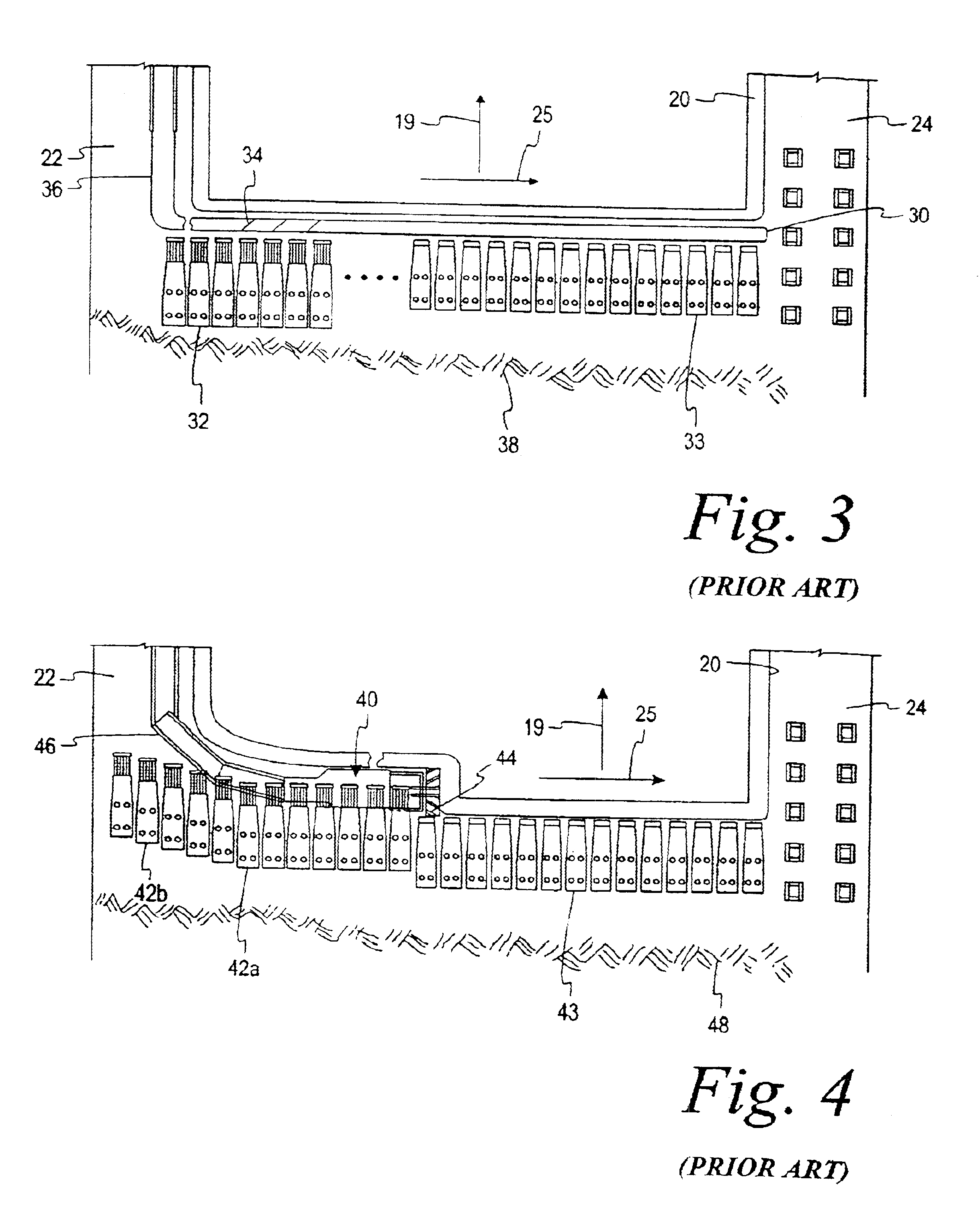
The only significant disadvantage of the shortwall mining system is that the production rate is somewhat lower as compared to the longwall mining system.
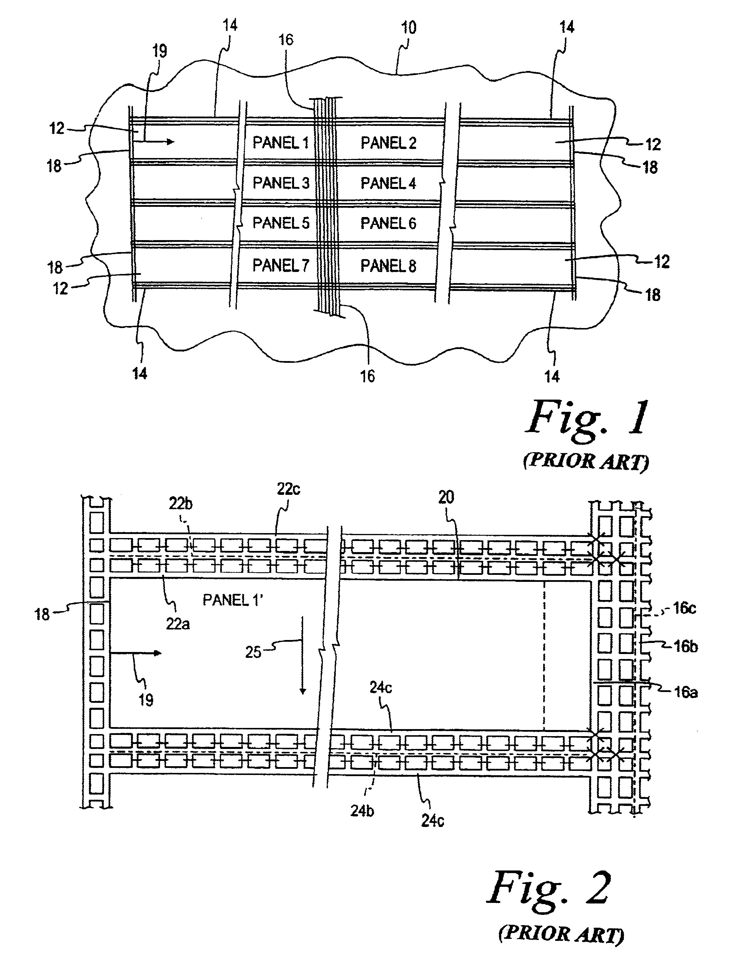
It should be apparent from the above, the primary problem associated with underground longwall and shortwall mining systems is the cost and time associated with developing and creating the panels, and then moving either system from panel to panel underground to mine the entire mineral reserve 10.
The moves from panel to panel result in many days of downtime at a high cost to the mining operation.
The ingress and egress entries and ventilation associated with the system are all expensive.
Time travel to the seam face for the miners is also a significant cost associated with these systems.
Moreover, federal legislation (e.g., Clean Water Act) restricts the use of waste rock produced by large scale surface mining systems as “fill material” legitimately disposed of at other locations.
Thus, the disposal of excess spoil is a significant problem.
Finally, certain mining areas may have property limitations, such that only one side of the mining area is controlled through lease or ownership, while the other side of the mining area is not controlled.
This creates a tremendous burden on miners who wish to utilize mineral reserves under their control.

Method used


Image

  • Mining system
  • Mining system
  • Mining system

Examples


Embodiment Construction

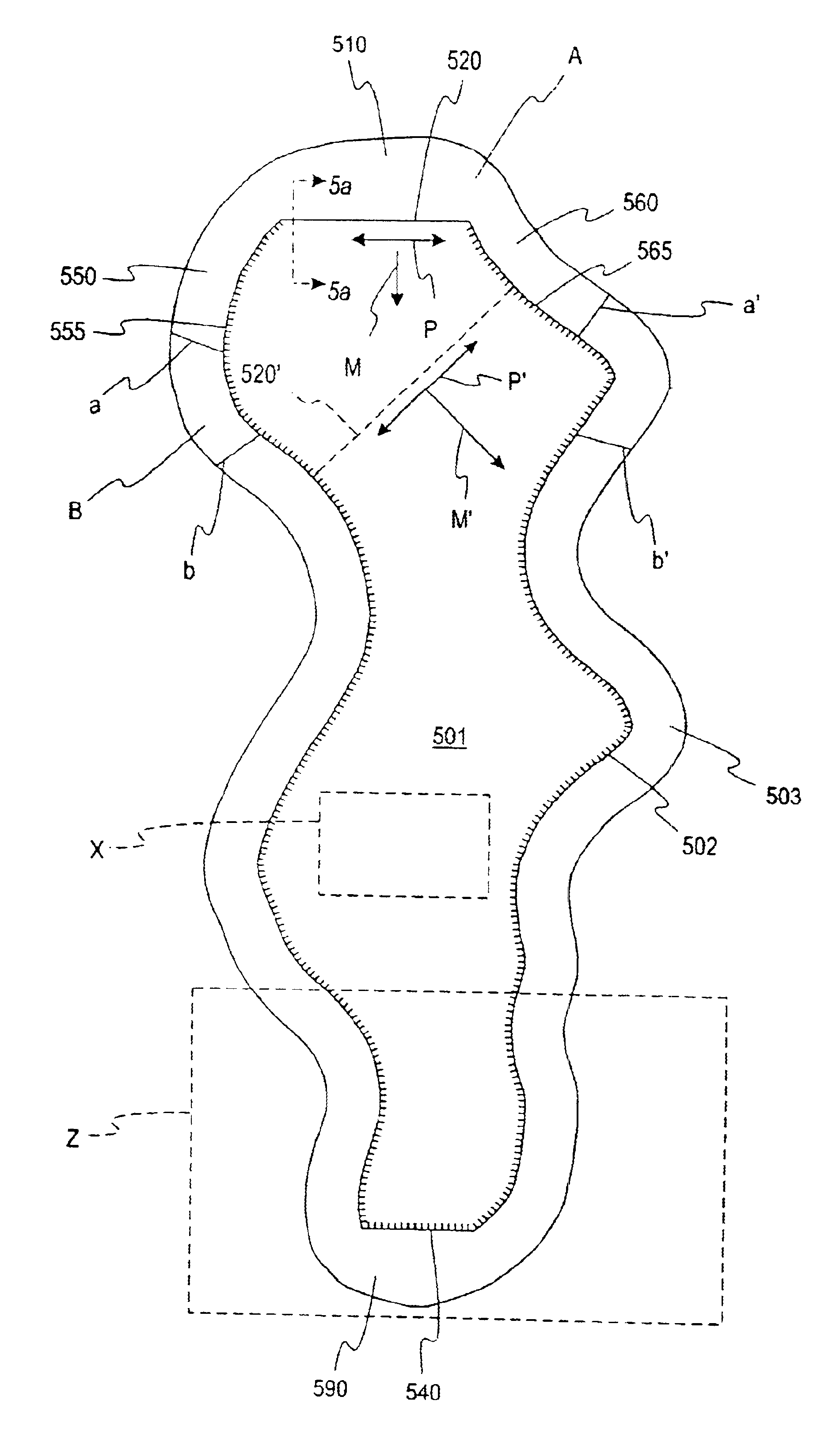
[0046]The present invention provides an economical, convenient mining system adapted to quickly and efficiently remove mineral deposits from a mineral reserve with minimal downtime. Apparatus and methods for extracting the mineral deposits are provided by combining surface contour mining with underground longwall or shortwall mining techniques. Referring more specifically to a mineral reserve 501 in FIG. 5, the mining system of the present invention utilizes surface contour mining to create a stable highwall 502 and bench area 503 around the mineral reserve 501 to allow insertion of the mining system underground. The surface contour mining, however, is conducted in stages commencing with mining area A between lines a and a′, then mining area B advancing to lines b and b′, followed by subsequent surface contour cuts advancing in increments of about 200 feet to 500 feet for each mining area to the end of the mineral reserve 501. The bench area 503 is typically between 80 to 100 feet w...


PUM


Abstract

A method for extracting mineral deposits in a mineral reserve, a portion being accessible from a sloping surface and the remaining portion being inaccessible, is disclosed. The sloping surface is mined to create a bench and highwall for providing access to the mineral reserve around the accessible portion. Then, a surface is formed in the highwall to create an insertion highwall between an endwall extending from the insertion highwall and the inaccessible portion of the mineral reserve. A starter entry is created for cutting into the mineral reserve across the entire length of the insertion highwall from the endwall to the inaccessible portion of the mineral reserve. Roof supports are advanced into the starter entry with spoil added to form a starter passage from the endwall to the inaccessible portion of the mineral reserve. Shortwall or longwall mining techniques are then used to mine the mineral reserve along the starter passage. Canopies are positioned at both ends of the starter passage to seal the passage and provide ventilation of the active mining area by the introduction of air along the face of the mineral seam. A single-gate passage is formed extending from the insertion highwall adjacent the inaccessible portion of the mineral reserve to allow the continuous miner to form another opposing endwall. Mining then continues in the starter passage along the insertion highwall from the single-gate passage to the opposing endwall, thereby forming a production passage into which the roof supports are farther advanced with gob forming behind.

Description

CROSS-REFERENCE TO RELATED APPLICATION[0001]This Nonprovisional application for patent is a Continuation-In-Part of U.S. Nonprovisional Application for patent Ser. No. 10 / 183,741, filed on Jun. 26, 2002, and is hereby incorporated by reference in its entirety herein.FIELD OF THE INVENTION[0002]The present invention relates, in general, to a mining system for extracting mineral deposits, and more specifically, but without limitation, to a mining system utilizing a combination of surface contour mining and underground shortwall or longwall mining systems.BACKGROUND OF THE INVENTION[0003]Conventional surface mining systems have devastating environmental results. In hilly or mountainous regions, surface contour mining is accomplished by removing timber and clearing the area to be mined, making a strip cut to form a substantially horizontal bench and a vertical highwall that exposes the seam of mineral deposits to be removed. Another technique is to simply remove the entire top portion o...

Claims


Application Information

Patent Timeline
Patent Type & Authority Patents(United States)
IPC IPC(8): E21C41/16E21C41/00E21C41/26
CPCE21C41/16E21C41/26E21C41/32
Inventor HARMAN, JEFFREY K.HARMAN, JOEY W.
Owner CLECO CORP
Learn More