Electrically operable vehicle parking brake drive

Active Publication Date: 2005-07-05
ELLCON NAT
View PDF5 Cites 26 Cited by
  • Summary
  • Abstract
  • Description
  • Claims
  • Application Information

AI Technical Summary

Benefits of technology

[0018]The proximity sensor and the limit switch are mounted in the drive housing. The proximity sensor is responsive to movement of one of the interengageable members by the hand wheel control and causes t

Problems solved by technology

The requirement of being able to apply 125 pounds to the hand wheel is quite demanding.
A weaker person cannot readily release the hand brake if a stronger person has applied it.
Therefore, the drive requires two ratchet wheel and pawl mechanisms and two electrically operable, physically movable components in the housing which is subject to the accumulation of dust, grease, etc.
In addition, if the manual

Method used


Image

  • Electrically operable vehicle parking brake drive
  • Electrically operable vehicle parking brake drive
  • Electrically operable vehicle parking brake drive

Examples


Embodiment Construction

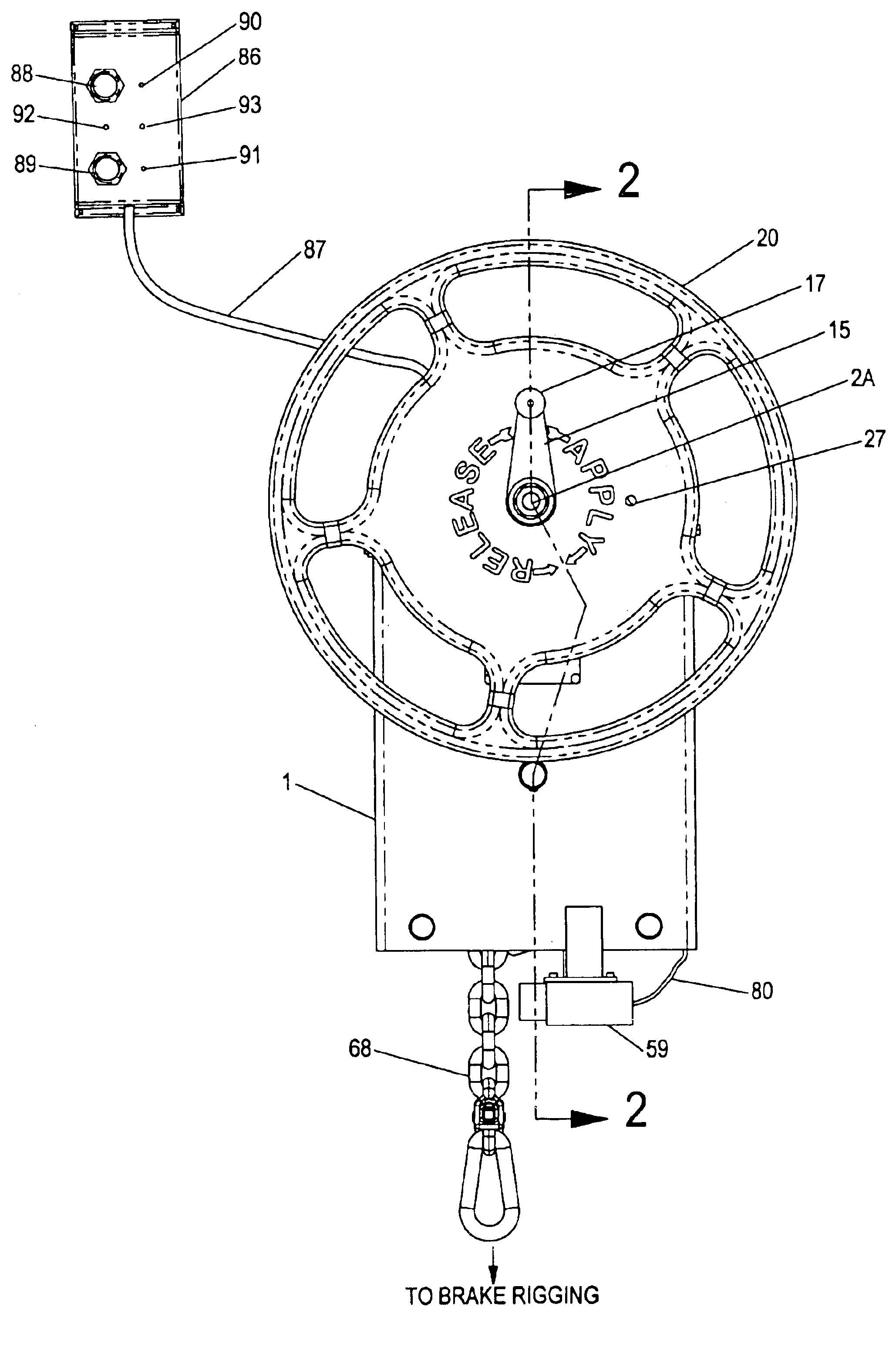
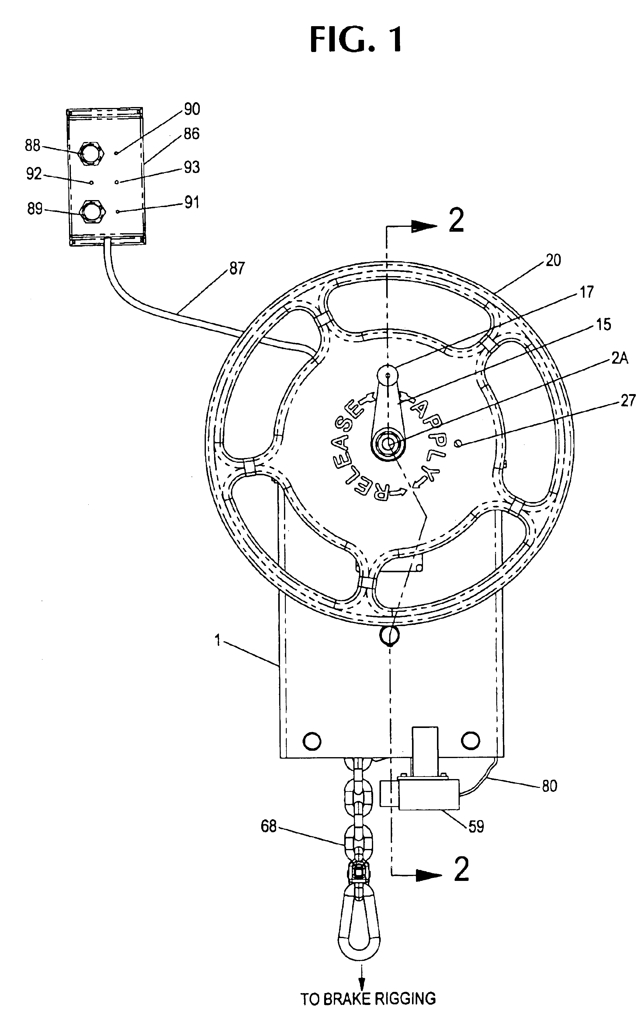
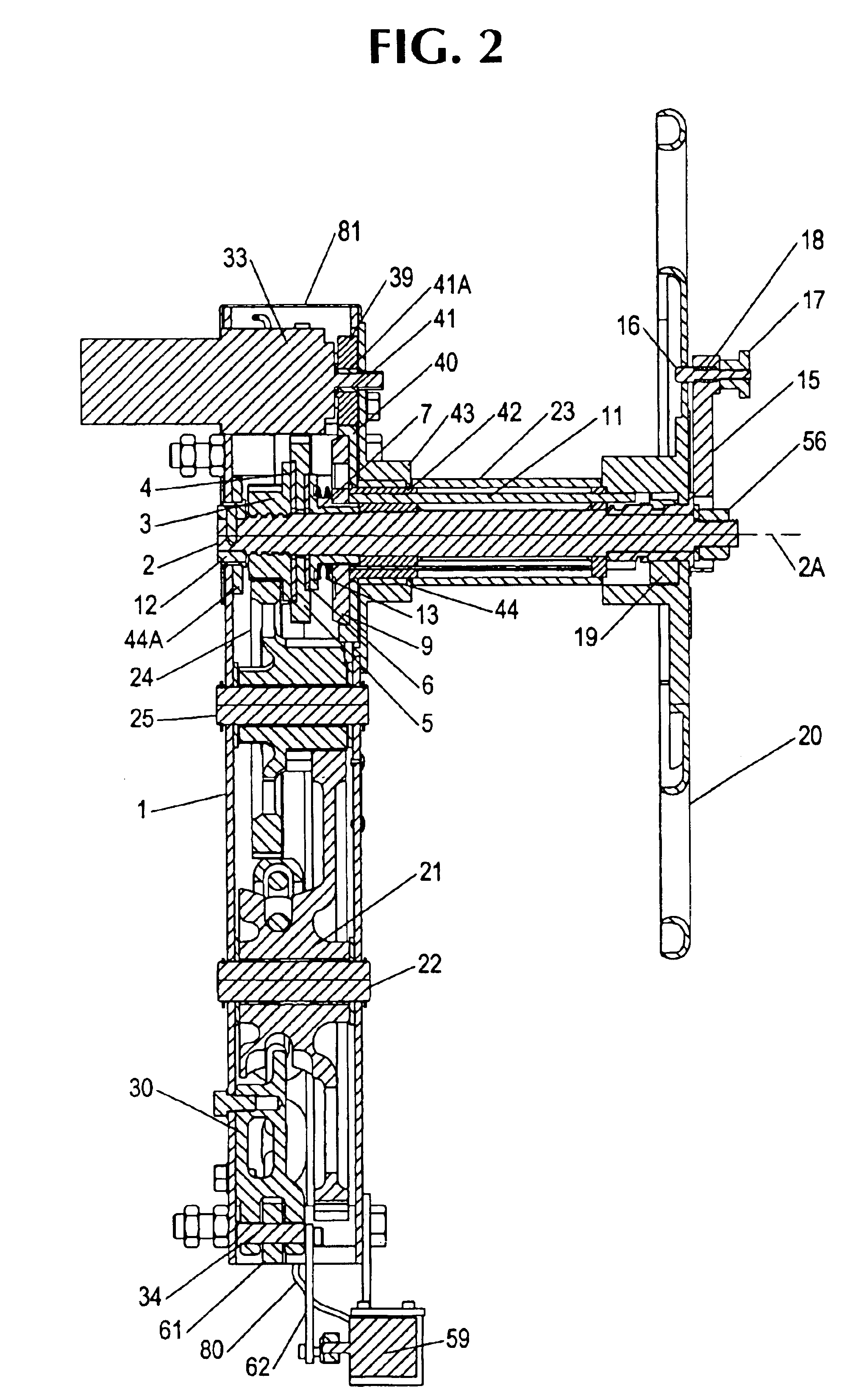
[0032]Although the invention can be used with other types of parking brake drives, the invention will be described in connection with a drive known in the art as a gradual release mechanism or drive for hand operable parking brakes, such as the drive described in U.S. Pat. No. 2,618,169. The latter drive is advantageous in that the brakes can be gradually released manually and the hand wheel does not spin out of control of the operator when the brakes are being released. In the preferred embodiment of the invention, the brakes can be “set” or “released” either by energizing an electric motor or by manual operation of a manually operable member, e.g. a hand wheel. In the electrical operating mode, the hand wheel can remain stationary, and the brakes can be set or released remotely from the drive, i.e. without any manual change or adjustment of the drive. In the manual operating mode, the electric motor is mechanically disconnected from the gear which is connected to the brakes so tha...


PUM


Abstract

An electrically or manually operable brake drive for the brakes of a vehicle which has a gear train optionally driven by a reversible electric motor or a manual member. The brakes can be set or released by the electric motor without manual changing of the drive components permitting setting and releasing of the brakes at a location remote from the drive. For maintaining the brakes in a “set” mode, the drive includes a gradual release detent mechanism which permits rotation of the gears in the brake setting direction but opposes such rotation in the opposite direction unless a drive shaft rotatable by the motor or the manual member is rotated in the brake release direction.

Description

RELATED APPLICATION[0001]The benefit of priority of provisional application No. 60 / 445,166 filed Feb. 5, 2003 is claimed and the application is incorporated herein by referenceFIELD OF THE INVENTION[0002]The invention relates to a drive for the braking apparatus of a vehicle with wheels. The drive is operable either manually or by an electric motor. Such a drive operable only manually is commonly known as a hand brake or a parking brake.BACKGROUND OF THE INVENTION[0003]Although applicable to other types of vehicles, the invention will be described in connection with railroad or railway vehicles, such as railway cars, locomotives, etc.[0004]Railway vehicles usually have brake shoes engageable with the vehicle wheels. Such shoes are forced against the wheels by an air operable piston and cylinder assembly acting through a brake rigging mounted on the vehicle and connected to the shoes. Such brake shoe operation is used to slow the vehicle down or to bring the vehicle to a halt.[0005]H...

Claims


Application Information

Patent Timeline
IPC IPC(8): B60T13/66B61H13/04B61H13/00
CPCB60T13/665B61H13/04
Inventor MICHEL, MARKSHEPHERD, ROBERTWASNESS, JAMES
Owner ELLCON NAT
Why Eureka
Try Eureka