Turbine blade ring assembly and clocking method

a technology of turbine blades and clocking methods, which is applied in the direction of machines/engines, stators, liquid fuel engines, etc., can solve the problems of time-consuming, labor-intensive, and high cost of removal and/or disassembly, and achieve the effect of facilitating the rotation of the blade ring

Inactive Publication Date: 2005-07-05
SIEMENS ENERGY INC
View PDF19 Cites 28 Cited by
  • Summary
  • Abstract
  • Description
  • Claims
  • Application Information

AI Technical Summary

Benefits of technology

[0017]The at least one access panel is removed. A first actuator is attached to one attachment of a first pair of attachments; a second actuator is attached to the other attachment of the first pair of attachments. The first and second actuators can be one of cables or chains. The blade ring is then rotated by substantially simultaneously pulling the first and second actuators so as to impart substantially tangential forces on the blade ring. Rotation of the blade ring is facilitated by engagement of the outer peripheral surface of the blade ring with the roller pins.

Problems solved by technology

However, current clocking methods require the disassembly and / or removal of at least a substantial portion of the outer turbine casing that encloses the blade ring and to which the blade ring is attached.
Such removal and / or disassembly can be expensive, time consuming, and labor intensive.

Method used


Image

  • Turbine blade ring assembly and clocking method
  • Turbine blade ring assembly and clocking method
  • Turbine blade ring assembly and clocking method

Examples


Embodiment Construction

[0022]Aspects of the present invention address the shortcoming associated with prior blade ring configurations and clocking methods. Aspects of the present invention relate to a method for clocking a turbine blade ring so as to position a row of vanes relative to at least a preceding and / or subsequent row of airfoils. Other aspects of the present invention are directed to a turbine blade ring configuration that can facilitate such methods.

[0023]Embodiments of the invention will be explained in the context of one possible turbine configuration, but the detailed description is intended only as exemplary. Embodiments of the invention are shown in FIGS. 1–4, but the present invention is not limited to the illustrated structure or application.

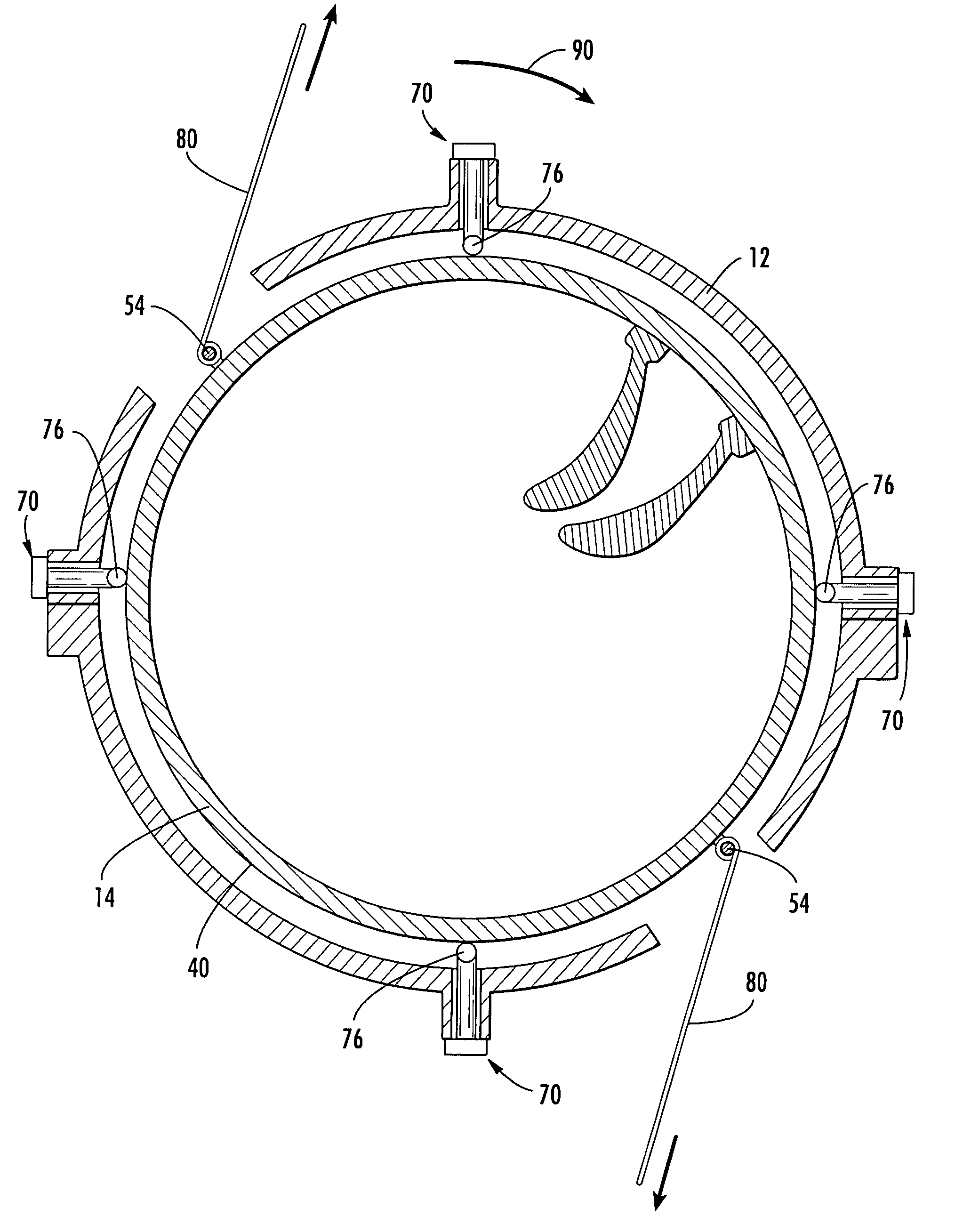
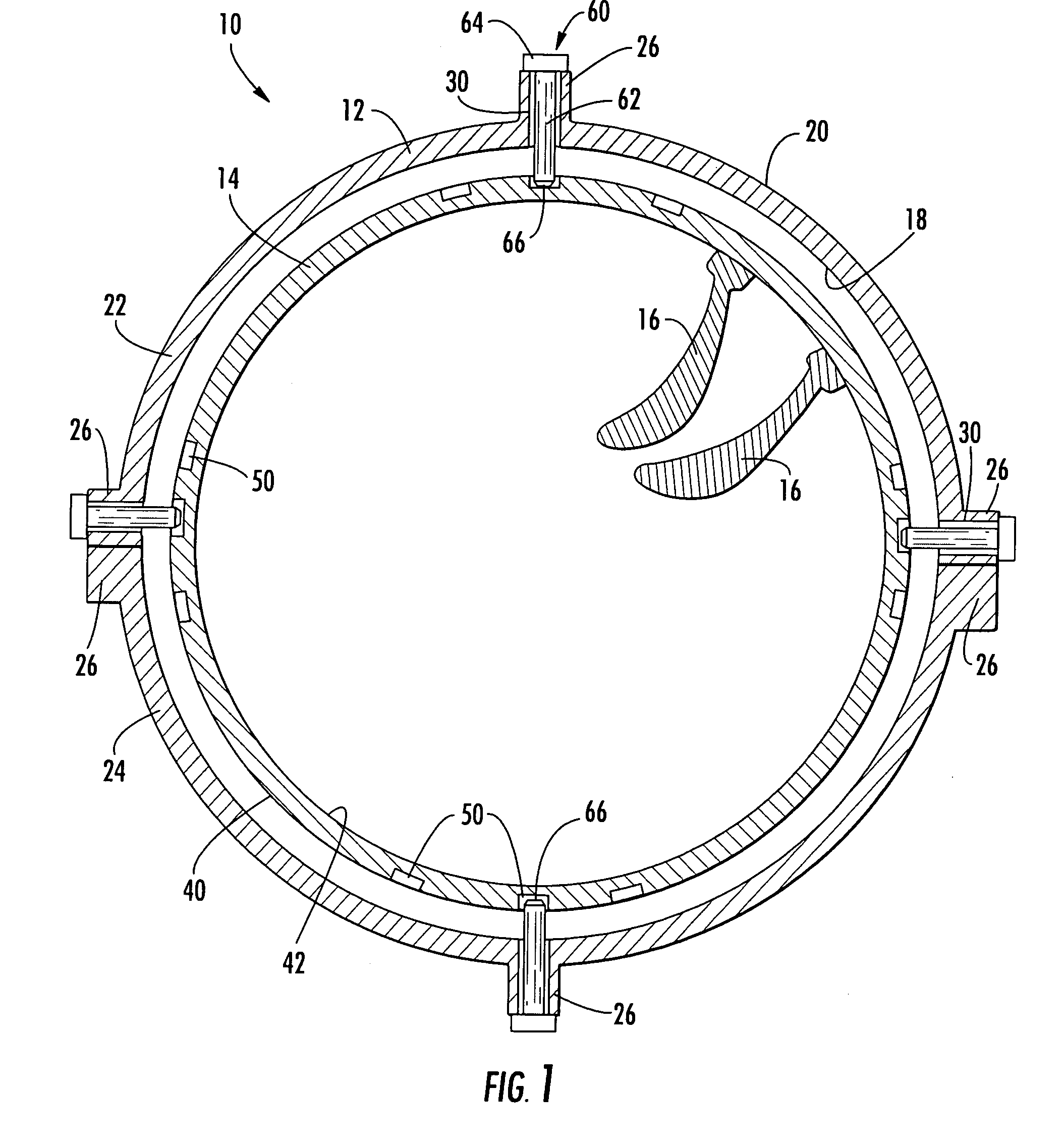
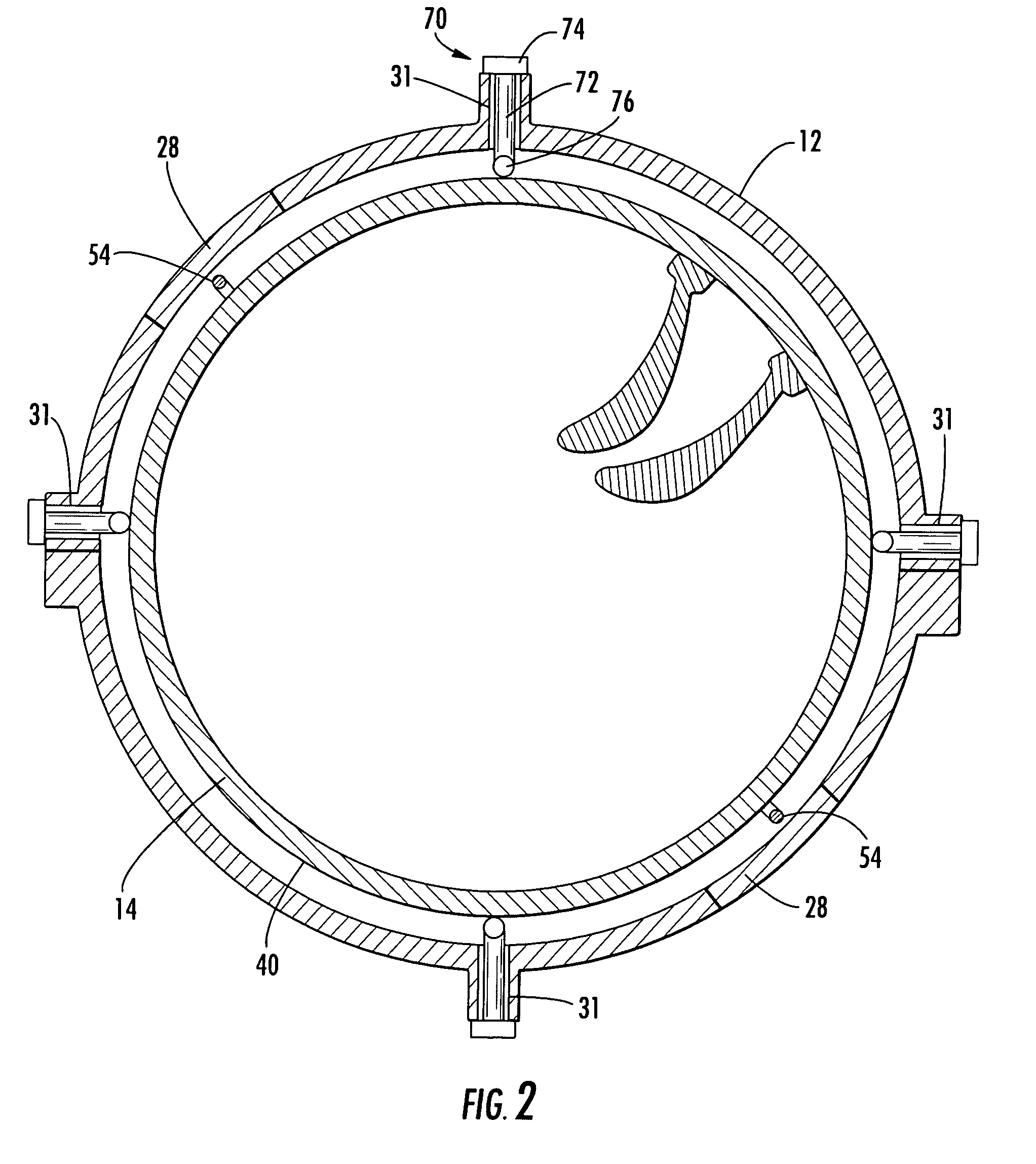
[0024]An example of a turbine assembly 10, configured according to aspects of the invention, is shown in FIG. 1. The turbine assembly 10 can include a variety of components such as an outer casing 12, a blade ring 14 held in substantially fixed rela...


PUM


Abstract

Aspects of the invention relate to a method for clocking a row of stationary airfoils relative to an adjacent row of airfoils, and a turbine blade ring configured for use in such a method. The method according to aspects of the invention is advantageous because it can avoid extensive disassembly of the turbine in order to clock the blade ring. The method includes engaging the outer peripheral surface of a blade ring with a plurality of roller pins such that the weight of the blade ring is entirely supported by the roller pins. A tangential force is applied to the blade ring such that the blade ring rotates on the roller pins, thereby adjusting the position of the stationary airfoils affixed to the blade ring. Additional rotational adjustments can be made to the blade ring until the blade ring is clocked to the desired position.

Description

FIELD OF THE INVENTION[0001]The invention relates in general to turbine engines and, more particularly, to a turbine blade ring or vane carrier configuration and a method for clocking a row of stationary airfoils.BACKGROUND OF THE INVENTION[0002]The turbine section of a turbine engine includes one or more rows of stationary airfoils, commonly referred to as vanes or stationary blades. In some applications, each row comprises a plurality of vanes that are affixed to the inner periphery of a blade ring or other vane carrier. The rows of vanes are interspaced between rows of rotating airfoils, commonly referred to as blades. The relative positioning of two rows of airfoils, known as the clocking, can affect the efficiency of the turbine.[0003]One method for clocking a row of airfoils is to rotate the blade ring so as to change the position of the attached airfoils. However, current clocking methods require the disassembly and / or removal of at least a substantial portion of the outer tu...

Claims


Application Information

Patent Timeline
Patent Type & Authority Patents(United States)
IPC IPC(8): F01D25/24F01D9/04
CPCF01D9/041F01D25/246
Inventor FADOK, JOSEPH J.
Owner SIEMENS ENERGY INC
Why Eureka
Try Eureka