Profile control platen

a technology of profile control and plate, which is applied in the direction of grinding heads, manufacturing tools, lapping machines, etc., can solve the problems of inability to properly focus the light image onto the entire outer surface, the rate of polishing is variable, and the non-planar outer surface presents a problem for the integrated circuit manufacturer, etc., to achieve the effect of improving the control of the polishing rate and lowering the polishing ra

Inactive Publication Date: 2005-07-05
APPLIED MATERIALS INC
View PDF10 Cites 23 Cited by
  • Summary
  • Abstract
  • Description
  • Claims
  • Application Information

AI Technical Summary

Benefits of technology

[0011]Particular implementions of the invention can realize one or more of the following advantages. The invention can provide improved control of polishing rates across the substrate surface (ie., polishing profile control). The backside of the polishing pad can be pressurized and the pressure can be applied at selected regions of the polishing pad. The location of the selected pressurized regions relative to the substrate can be varied by varying the location of the substrate relative to the polishing pad. More pressure can be applied in regions of the substrate where the polishing rate is lower. The polishing pad can transfer pressure to the front surface of the substrate substantially without distortion, e.g., spreading, of the shape or size of the selected region.

Problems solved by technology

This non-planar outer surface presents a problem for the integrated circuit manufacturer.
Then it will be impossible to properly focus the light image onto the entire outer surface.
However, a variety of factors, including non-uniform velocities, non-uniform slurry distribution and distortions in the polishing pad can cause the rate of polishing to vary spatially, resulting in non-uniform polishing of a semiconductor substrate surface.

Method used


Image

  • Profile control platen
  • Profile control platen
  • Profile control platen

Examples


Embodiment Construction

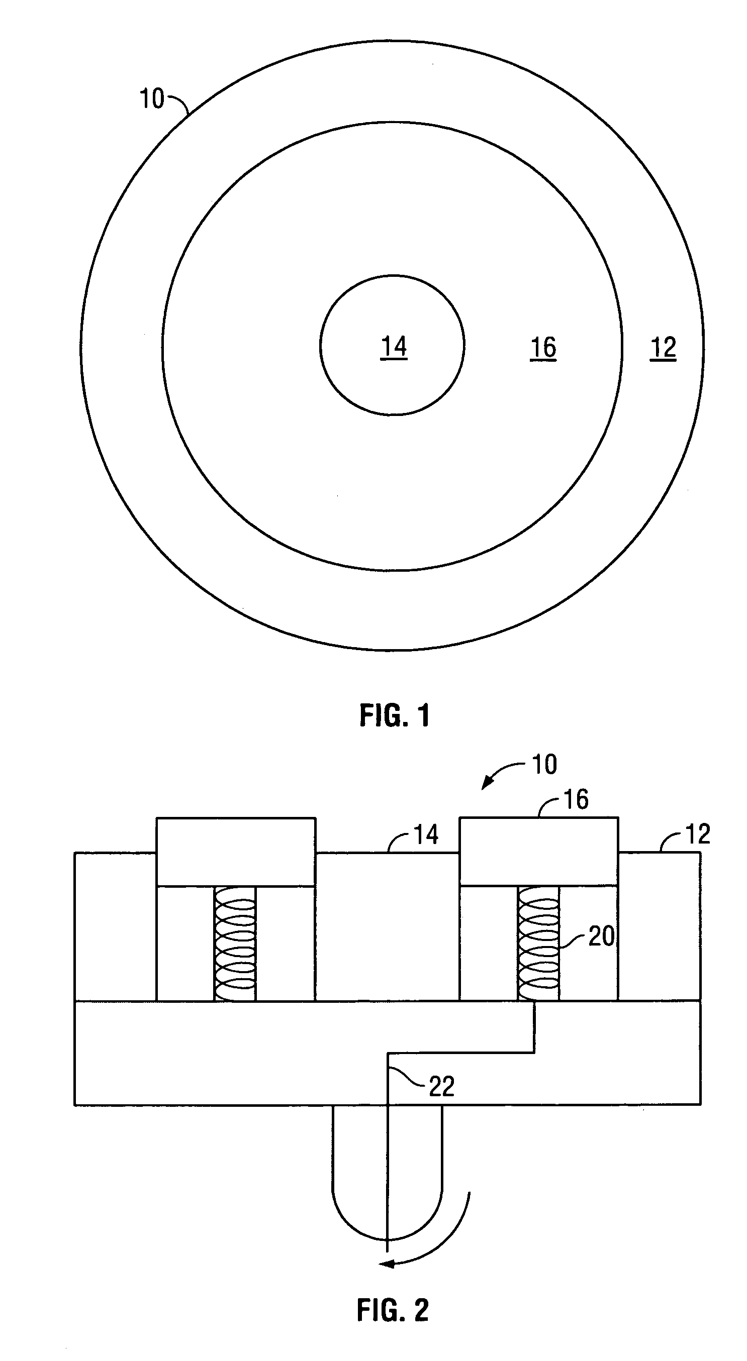
[0020]Referring to FIG. 1, a chemical mechanical polishing apparatus includes a rotatable platen 10 for supporting a polishing pad (not shown). In other respects, the CMP apparatus can be configured as described in U.S. Pat. No. 5,738,574, the entire disclosure of which is incorporated by this reference.

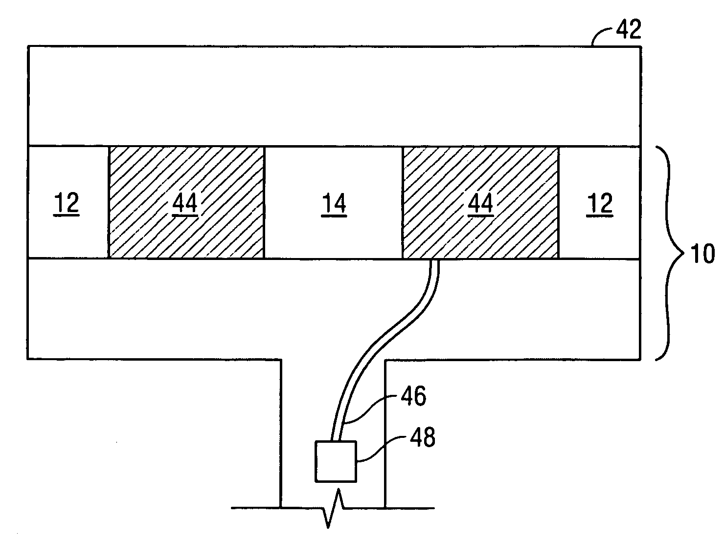
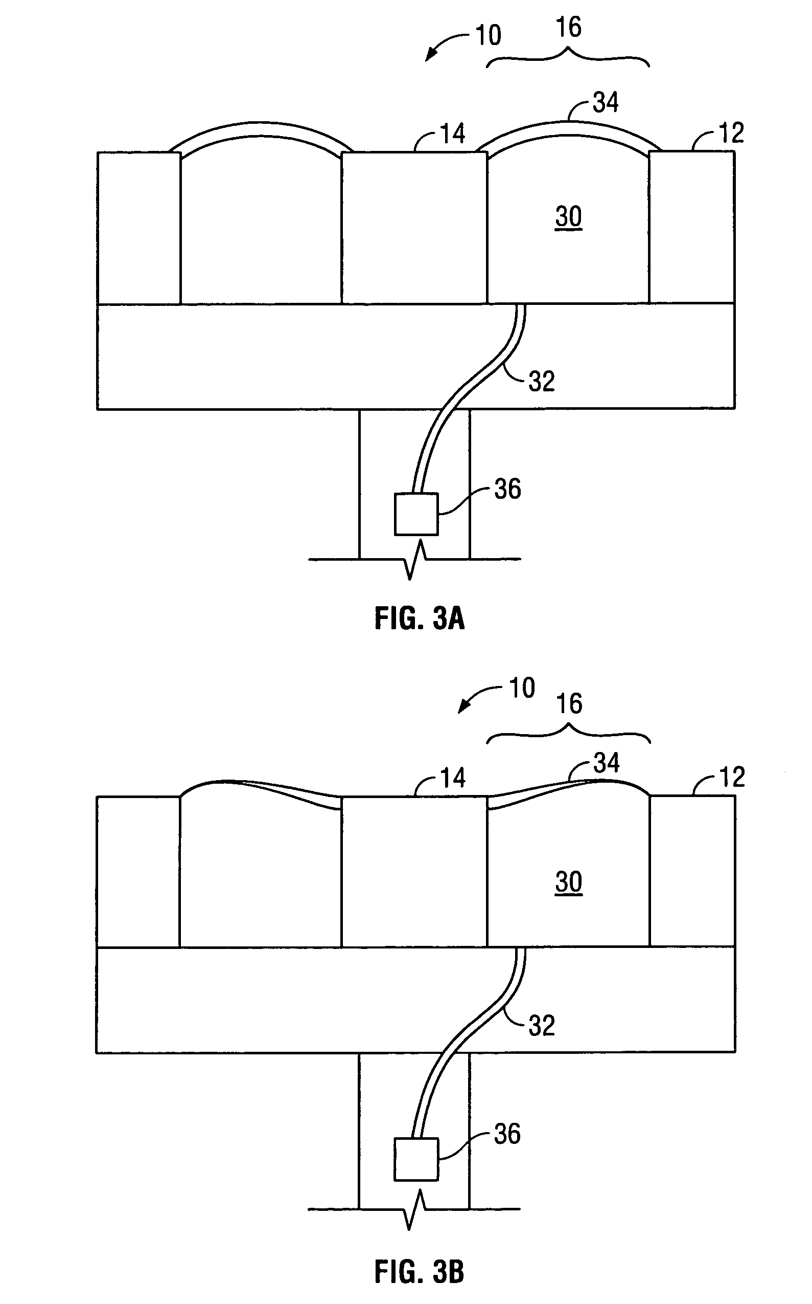
[0021]The surface of the platen 10 can include an outer region 12, a center region 14, and a middle region 16 that lies in between the outer region 12 and center region 14. In one implementation, the surface of the platen 10 can be shaped as a circle. The center 14, middle region 16, and outer 12 regions can represent radial regions of the circular surface, with the circular center region 14 being closest to the center, the annular outer region 12 being furthest from the center and the annular middle region 16 being between the annular outer 12 and the circular center 14. The amount of pressure that the platen exerts against the polishing pad can vary among regions of the platen. A g...


PUM

PropertyMeasurementUnit
thickaaaaaaaaaa
thickaaaaaaaaaa
forceaaaaaaaaaa

Abstract

A platen for chemical mechanical polishing of a substrate includes a surface upon which a polishing pad can be placed, a support structure, and a controller. The surface has a first region and a second region and is operable to exert force against the polishing pad during polishing. The support structure is located beneath the second region and is operable to cause the second region to exert more force than the first region. The controller is operable to adjust the amount of force that is exerted by the second region.

Description

BACKGROUND[0001]The present invention relates generally to chemical mechanical polishing of substrates.[0002]Integrated circuits are typically formed on substrates, particularly silicon wafers, by the sequential deposition of conductive, semi-conductive or insulating layers. After each layer is deposited, the layer is etched to create circuitry features. As a series of layers are sequentially deposited and etched, the outer or uppermost surface of the substrate, i.e., the exposed surface of the substrate, becomes increasingly non-planar. This non-planar outer surface presents a problem for the integrated circuit manufacturer. If the outer surface of the substrate is non-planar, then a photo-resist layer placed thereon is also non-planar. A photo-resist layer is typically patterned by a photolithographic apparatus that focuses a light image onto the photo-resist. If the outer surface of the substrate is sufficiently non-planar, the maximum height difference between the peaks and vall...

Claims


Application Information

Patent Timeline
Patent Type & Authority Patents(United States)
IPC IPC(8): B24B41/00B24B37/04B24B41/047B24B37/16
CPCB24B37/16
Inventor CHEN, HUNG CHIHZUNIGA, STEVEN M.GARRETSON, CHARLES C.OSTERHELD, THOMAS H.KO, SEN-HOUSALEK, MOHSEN
Owner APPLIED MATERIALS INC
Why Eureka
Try Eureka