Method of installing solar cell modules, and solar cell module

a technology of applied in the field of installing solar cells and solar cells, can solve the problems of increasing the number of process steps to be performed for wiring, and the inconvenience of installation, so as to reduce the time and cost of constructing a photovoltaic power generation system and ensure the effect of installation efficiency

Inactive Publication Date: 2005-07-05
SANYO ELECTRIC CO LTD
View PDF16 Cites 54 Cited by
  • Summary
  • Abstract
  • Description
  • Claims
  • Application Information

AI Technical Summary

Benefits of technology

[0011]An object of the present invention is to provide a solar cell module installation method capable of reducing the time and cost of constructing a photovoltaic power generation system and of realizing efficient installation according to an installation surface.
[0012]Another object of the present invention is to provide a solar cell module capable of obtaining long-term reliability.
[0013]A solar cell module installation method according to the first aspect is a method of installing a plurality of solar cell modules, wherein a plurality of types of solar cell modules having an equal output voltage and different sizes are installed so that they are connected in parallel. In other words, a plurality of types of solar cell modules that have an equal output voltage but have different sizes are installed in combination. Accordingly, by using large-size solar cell modules, it is possible to reduce the number of pieces of solar cell modules to be installed, shorten the construction time of a photovoltaic power generation system, decrease the number of parts such as terminal boxes and reduce the construction cost. Further, since solar cell modules having a size suitable for an installation space can be used, it is possible to realize efficient installation of the solar cell modules according to an installation surface.

Problems solved by technology

The conventional installation method suffers from the following problems.
Since the conventional method uses the solar cell modules of a fixed size, an extremely large number of solar cell modules must be installed for constructing a high-power photovoltaic power generation system and thus the number of processes to be performed for wiring increases and the total construction time is extremely long, and the construction cost also increases as an increased number of parts such as terminal boxes is required.
Moreover, since only solar cell modules of an equal size can be used, a plurality of solar cell modules can not be installed efficiently according to an installation surface.
In the conventional example, the wiring member for connecting the solar cell sub-modules to each other is sealed in the EVA resin layer so that it is shielded from outside air and has weather resistance, but it is hard to obtain long-term reliability by means of only the EVA resin layer.

Method used


Image

  • Method of installing solar cell modules, and solar cell module
  • Method of installing solar cell modules, and solar cell module
  • Method of installing solar cell modules, and solar cell module

Examples


first embodiment

(First Embodiment)

[0035]FIGS. 6A and 6B are illustrations showing the structures of two types of solar cell modules of the first embodiment for use in a solar cell module installation method of the present invention.

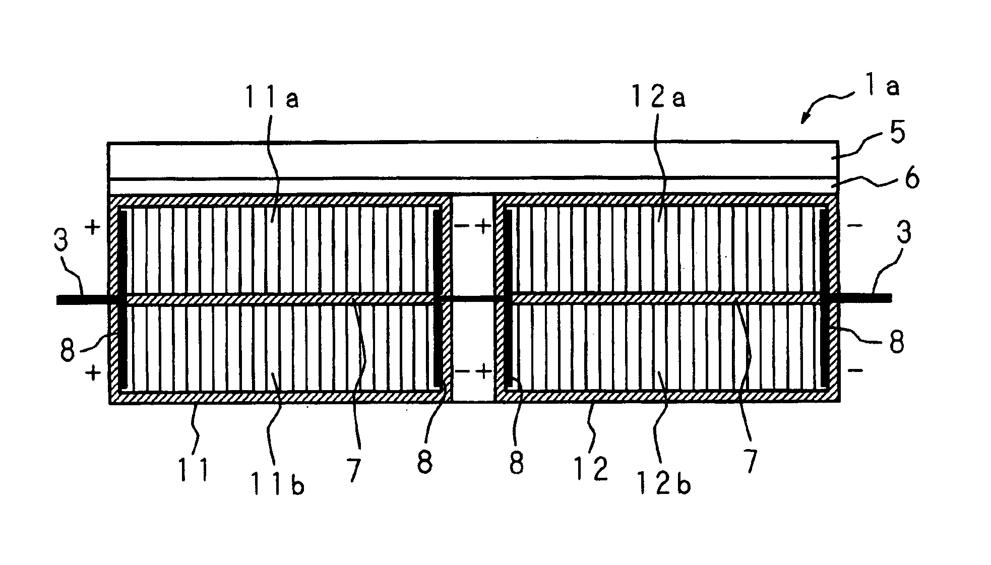
[0036]The solar cell module 1a shown in FIG. 6A is constructed by mounting two solar cell sub-modules 11 and 12 side by side on a steel plate 5 functioning as a support. In an area where the solar cell sub-modules 11 and 12 are not mounted, an engagement section 6 for engaging this solar cell module 1a with another solar cell module is formed unitedly by bending the steel plate 5.

[0037]The solar cell sub-modules 11 and 12 are divided into two power generating regions 11a and 11b or 12a and 12b by a laser separated portion 7. Each of these power generating regions 11a, 11b, 12a and 12b is constructed by connecting a plurality of solar cells in series so as to obtain a predetermined output voltage. The two power generating regions 11a and 11b of the solar cell sub-module 1...

second embodiment

(Second Embodiment)

[0042]FIGS. 8A and 8B are illustrations showing the structures of two types of solar cell modules of the second embodiment for use in a solar cell module installation method of the present invention.

[0043]The solar cell module 2a shown in FIG. 8A is constructed by mounting three solar cell sub-modules 21, 22 and 23 side by side on a steel plate 5. In an area where the solar cell sub-modules 21, 22 and 23 are not mounted, an engagement section 6 for engaging this solar cell module 2a with another solar cell module is formed unitedly by bending the steel plate 5.

[0044]Each of the solar cell sub-modules 21, 22 and 23 is divided into three power generating regions 21a, 21b and 21c, 22a, 22b and 22c, or 23a, 23b and 23c by laser separated portions 7. Each of these power generating regions 21a through 23c is constructed by connecting a plurality of solar cells in series so as to obtain a predetermined output voltage. The three power generating regions 21a-21c, 22a-22c a...

third embodiment

(Third Embodiment)

[0051]FIG. 11 is a plan view of an example of the structure of a solar cell module according to the third embodiment of the present invention, and FIG. 12 is a cross section cut along the A—A line of FIG. 11. In these figures, numeral 31 is a metal base made of stainless steel, for example. Two solar cell sub-modules 32 are mounted on the front surface of the metal base 31. Each of the solar cell sub-modules 32 comprises a glass substrate and a plurality of solar cells arranged on the glass substrate, and is mounted on the front surface of the metal base 31 through an EVA resin. In each solar cell sub-module 32, these plurality of solar cells are electrically connected to each other, and one positive wire 33 and one negative wire 33 which are respectively coated with an insulated tape are drawn from each solar cell sub-module 32.

[0052]A raised portion 37 having a first engagement section 37a at its end is formed at one edge of the metal base 31 where the solar cell...


PUM


Abstract

Two types of solar cell modules having an equal output voltage and different sizes are used, and a plurality of solar cell modules of these two types are installed so that they are connected in parallel. The size of a solar cell module having two solar cell sub-modules is two times larger than the size of a solar cell module including one solar cell sub-module. By connecting two power generating regions of each of the solar cell sub-modules of the former solar cell module in parallel, connecting adjacent two solar cell sub-modules in series and connecting two power generating regions of the solar cell sub-module of the latter solar cell module in series, an equal output voltage is obtained from both of the solar cell modules.

Description

BACKGROUND OF THE INVENTION[0001]The present invention relates to a method of installing a plurality of solar cell modules on an installation surface, such as the roof of a house, for photovoltaic power generation, and also relates to a solar cell module for use in a photovoltaic power generation system, particularly solar cell modules installed stepwise on buildings such as a house.[0002]Photovoltaic power generation for converting light energy into electrical energy by using a photoelectric conversion effect has been widely used as means for obtaining clean energy. Besides, with an improvement of the photoelectric conversion efficiency of solar cells, the number of private houses using a photovoltaic power generation system has been increasing.[0003]FIG. 1 is an illustration showing an ordinary structure of a photovoltaic power generation system. In FIG. 1, numeral 101 is a solar cell module designed to provide a predetermined output voltage by connecting a plurality of solar cell...

Claims


Application Information

Patent Timeline
Patent Type & Authority Patents(United States)
IPC IPC(8): G05F1/70H01L31/18H01L31/042H01L31/048H01L31/05
CPCH01L31/042H02S20/23Y02B10/12Y10S136/291Y02E10/50H01L31/02021Y02B10/10
Inventor TAKEDA, KATSUTOSHIKINOSHITA, TOSHIHIRO
Owner SANYO ELECTRIC CO LTD
Why Eureka
Try Eureka