Direction finding method and system using digital directional correlators

a technology of digital direction and direction finding, applied in direction finders, radio wave direction/deviation determination systems, instruments, etc., can solve the problems of large hardware cost, undesirable, large hardware cost, and difficulty in practical application of direction finding, and achieve high accuracy

Inactive Publication Date: 2005-07-05
NORTHROP GRUMMAN SYST CORP
View PDF7 Cites 32 Cited by
  • Summary
  • Abstract
  • Description
  • Claims
  • Application Information

AI Technical Summary

Benefits of technology

[0010]It is an object of the present invention to provide direction finding method and system which are capable of determining the angle of arrival of a wave-front with high accuracy using a few antenna elements, and requiring no dedicated circuit for the signal frequency determination. The method and system of the present invention are especially suitable for detecting distant radiating sources in the RF frequency bands.

Problems solved by technology

Disadvantages of this approach are that it requires the space to install multiple antennas, preferably in a coplanar geometry, and it requires extra antenna elements and receiver electronics to process the multiple baseline signals.
This represents a large hardware cost and is undesirable, especially, if the antenna array is to be installed in a limited space.
The direction finding problem is also difficult in practical application because the frequency of the incoming signal typically is not known before its reception at the direction finding system.
The main problem with this approach is that a relatively large number of digital channelizers are required, i.e., one for each antenna.

Method used


Image

  • Direction finding method and system using digital directional correlators
  • Direction finding method and system using digital directional correlators
  • Direction finding method and system using digital directional correlators

Examples


Embodiment Construction

[0036]Direction finding method and system according to the present invention are described. In the following detailed description, for purposes of explanation, numerous specific details are set forth in order to provide a thorough understanding of the present invention. It will be apparent, however, that the present invention may be practiced without these specific details. In other instances, well-known structures and devices are shown in block diagram form in order to simplify the drawing.

[0037]1. Mathematical Background

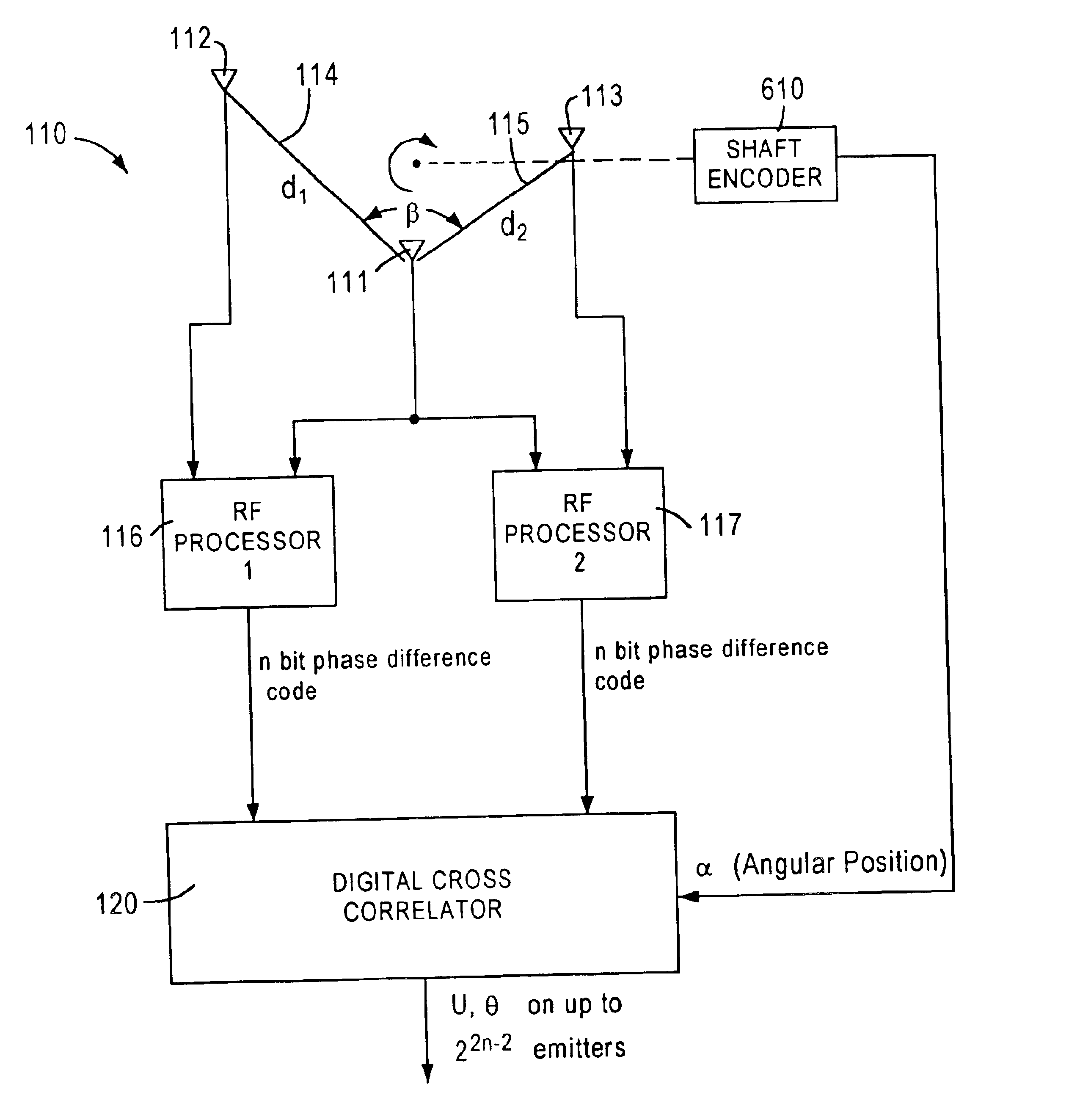
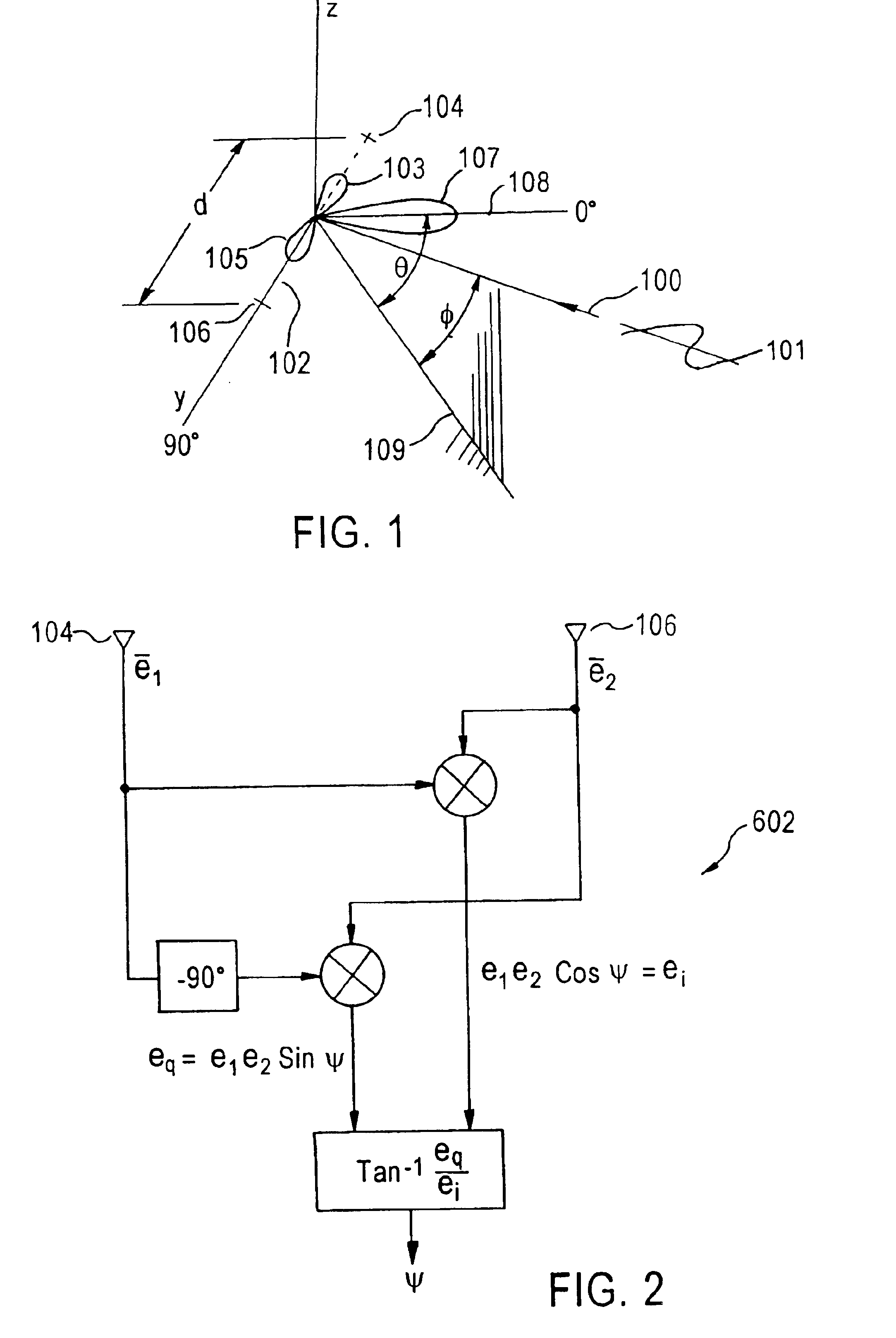
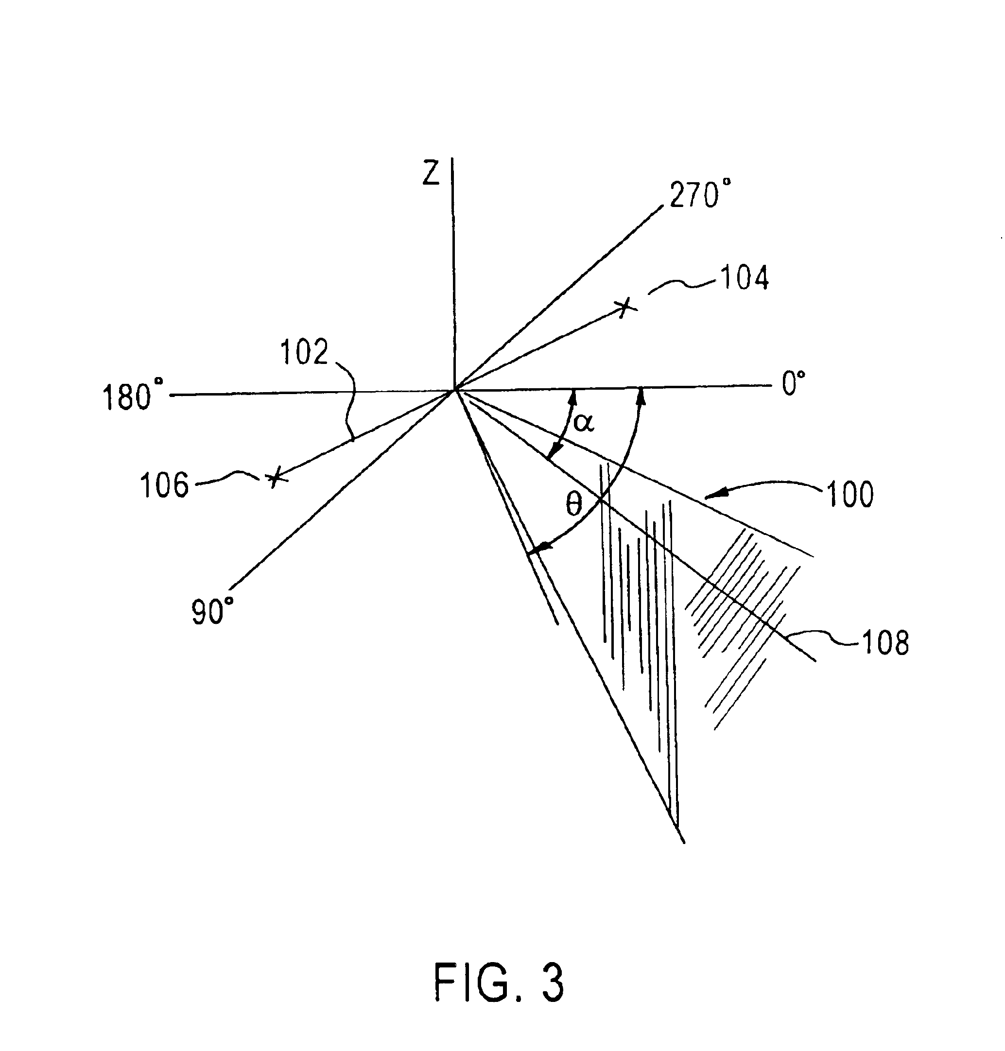
[0038]FIG. 1 is basic geometry showing the orientation of an electromagnetic wave-front 101 having a normal 100. Antenna array 102 comprises two receiving antennas 104, 106 spaced apart a known distance d to form a baseline of antenna array 102. The relative electrical phase, or phase difference, ψ, of the voltages induced in receiving antennas 104, 106 by the wave-front 101 is given by the following equation: ψ=2⁢ ⁢π⁢ ⁢dλ⁢ ⁢cos⁢ ⁢ϕ⁢ ⁢sin⁢ ⁢θ(1)

where ψ is the relat...


PUM


Abstract

In an interferometer system, a revolving antenna array is used to sufficiently resolve all ambiguities in determination of frequency and direction of arrival of a wave-front. The frequency and direction of arrival are determined by matching predicted phase difference codes with an actual code measured at the antenna array, utilizing a cross-correlation technique. The number of parameters that can be simultaneously uniquely determined by the system depends on if the antenna array is rotated in planar or conical surfaces, and if the cross-correlation is uni- or multi-dimensional. The antenna array may include more than one baselines to enhance the system sensitivity and finding capacity.

Description

FIELD OF THE INVENTION[0001]The present invention relates generally to direction finding systems, and in particular, to a digital direction finding method and system utilizing a revolving antenna array.BACKGROUND OF THE INVENTION[0002]The direction finding of electromagnetic transmission signals has been practiced for many years and has been achieved using a wide variety of antenna configurations and signal processing techniques. One such antenna configuration is a linear array of receiving antennas. Each receiving antenna has its own receiver circuit, and they are configured to simultaneously receive the transmission signal. At long distances, the radiating source appears as a point source, and the transmission signal from the point source appears as a planar wave-front to the linear array of a relatively small length.[0003]The simultaneously received signals from each receiving antenna are processed to determine the phase difference of the received signals between a pair of the re...

Claims


Application Information

Patent Timeline
Patent Type & Authority Patents(United States)
IPC IPC(8): G01S3/14G01S3/48G01S3/58
CPCG01S3/58G01S3/48
Inventor MARKS, MAURY I.
Owner NORTHROP GRUMMAN SYST CORP
Why Eureka
Try Eureka