Electrically small planar UWB antenna apparatus and related system

a planar antenna and antenna technology, applied in the direction of slot antennas, antenna details, antennas, etc., can solve the problems of loss, system ringing, and loss of transmission lines, and achieve the effect of mass-produced inexpensively, eliminating transmission line losses, dispersion and ringing

Inactive Publication Date: 2005-07-05
NORTH STAR INNOVATIONS
View PDF4 Cites 67 Cited by
  • Summary
  • Abstract
  • Description
  • Claims
  • Application Information

AI Technical Summary

Benefits of technology

[0009]In view of the foregoing, there exists a need in the art for a simple UWB antenna that has an unbalanced feed, and can be arrayed in 1D and 2D on a single substrate (i.e., planar or conformal). Additionally, there is a need for a UWB antenna that is electri

Problems solved by technology

As recognized by the present inventor, none of the above UWB antennas, however, provide high performance, non-dispersive characteristics in a cost-effective manner.
That is, these antennas are expensive to manufacture and mass-produce.
Additionally, these conventional antennas do not permit integration of radio transmitting and/or receiving circuitry (e.g., switches, amplifiers, mixers, etc.), thereby causing losses and system ringing (as further described below).
Another common problem as presently recognized by the inventor, is that most UWB antennas require balanced (i.e., differential) sources and loads, entailing additional manufacturing cost to overcome.
For example, the symmetry of the radiation pattern (e.g., azimuthal symmetry on a horizontally polarized dipole antenna) associated with balanced antennas can be poor because of feed imbalances arising from imperfect baluns.
Furthermore, the balun, instead of the antenna, can limit the antenna system bandwidth due to

Method used


Image

  • Electrically small planar UWB antenna apparatus and related system
  • Electrically small planar UWB antenna apparatus and related system
  • Electrically small planar UWB antenna apparatus and related system

Examples


Embodiment Construction

[0057]Referring now to the drawings, specific terminology will be employed for the sake of clarity. However, the present invention is not intended to be limited to the specific terminology so selected and it is to be understood that each of the elements referred to in the specification are intended to include all technical equivalents that operate in a similar manner. In addition, elements referred to by corresponding numbers, e.g., those that share the last two digits such as 105, 305, . . . , 2005, etc. are intended to refer to similar elements in the different embodiments.

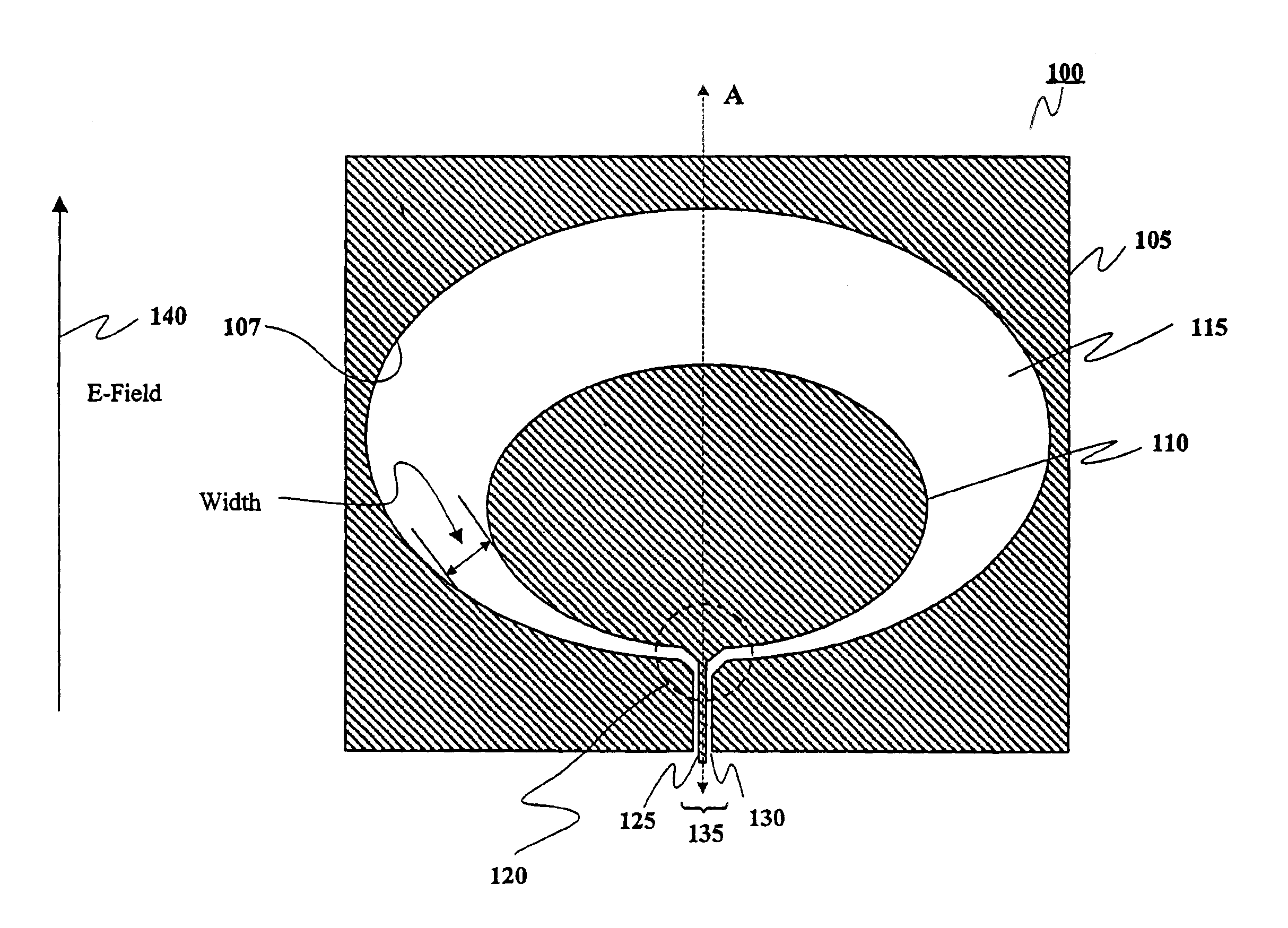
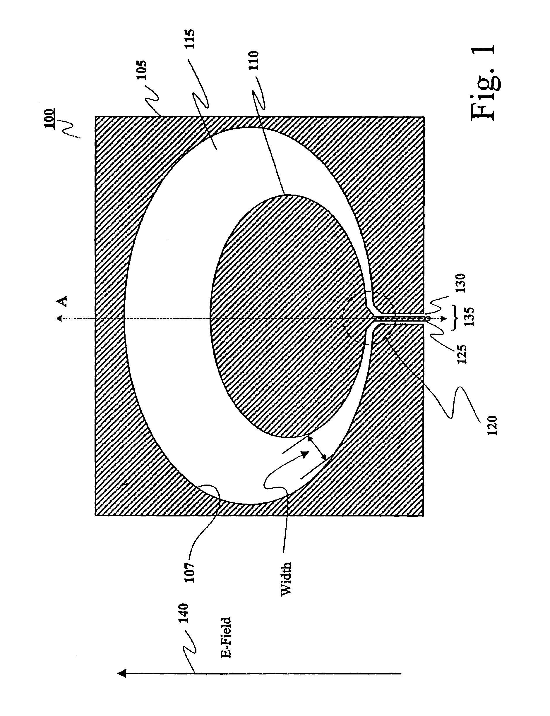
[0058]Referring now in detail to the drawings, FIG. 1 is a diagram of a UWB antenna according to an embodiment of the present invention. As seen in FIG. 1, the antenna 100 has a ground element (i.e., a ground plane) 105, a driven element 110, a tapered clearance area 115 between the ground element 105 and the driven element 110, a feed point 120, a transmission line 125, and an antenna input 135.

[0059]In this em...


PUM


Abstract

An electrically small, planar ultra wide bandwidth (UWB) antenna is disclosed. The antenna has a conductive outer ground area that encompasses a tapered non-conducting clearance area, which surrounds a conductive inner driven area. The feed is unbalanced with the terminals are across the narrowest part of the non-conducting clearance area which is tapered to provide a low VSWR across ultra wide bandwidths exceeding 100%. The antenna can be arrayed in 1D and 2D on a single common substrate. Amplifiers can be readily mounted at the feed.

Description

CROSS-REFERENCE TO RELATED PATENT DOCUMENTS[0001]This application is a continuation of U.S. patent application Ser. No. 10 / 054,790, filed Jan. 25, 2002 now U.S. Pat. No. 6,590,545, and entitled “Electrically Small Planar UWB Antenna Apparatus and System,” which is a continuation-in-part of U.S. patent application Ser. No. 09 / 633,815, filed Aug. 7, 2000 now abandoned, and entitled “Electrically Small Planar UWB Antenna Apparatus and System Thereof, which is related to U.S. patent application Ser. No. 09 / 209,460 filed on Dec. 11, 1998 and entitled “Ultra Wide Bandwidth Spread-Spectrum Communications System,” all of which are incorporated herein by reference in their entirety.BACKGROUND OF THE INVENTION[0002]The present invention relates generally to antenna apparatuses and systems, and more particularly, to planar antennas with non-dispersive, ultra wide bandwidth (UWB) characteristics.[0003]With respect to the antenna of radar and communications systems, there are five principle char...

Claims


Application Information

Patent Timeline
IPC IPC(8): H01Q15/00H01Q13/08
CPCH01Q13/085H01Q15/006
Inventor MCCORKLE, JOHN W.
Owner NORTH STAR INNOVATIONS
Why Eureka
Try Eureka