Electrically small octave bandwidth non-dispersive uni-directional antenna

a non-dispersive, uni-directional antenna technology, applied in the direction of elongated active element feed, resonant antenna, radiating element structure, etc., can solve the problems of inability to afford the cost of adding inverse filtering components, inability to manufacture and mass produce antennas, and inability to provide high bandwidth, non-dispersive characteristics in an electrically small size and cost-effective manner. , to achieve the effect of low cost, wide bandwidth and low disper

Inactive Publication Date: 2012-06-21
MCCORKLE JOHN W
View PDF7 Cites 12 Cited by
  • Summary
  • Abstract
  • Description
  • Claims
  • Application Information

AI Technical Summary

Benefits of technology

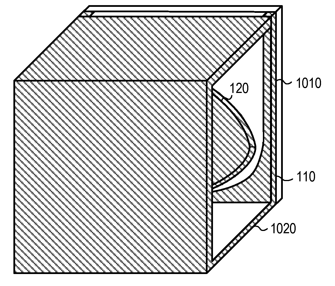
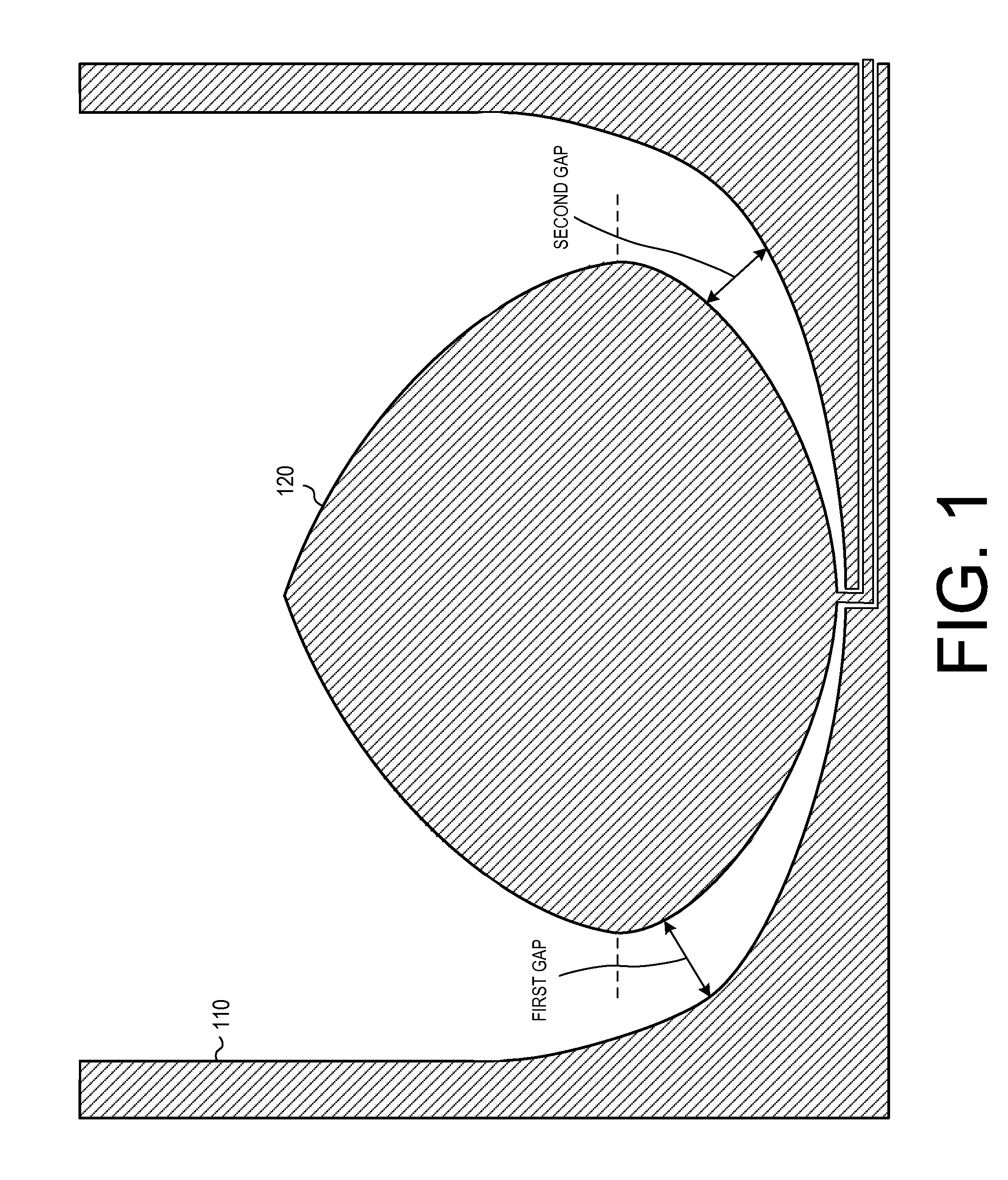
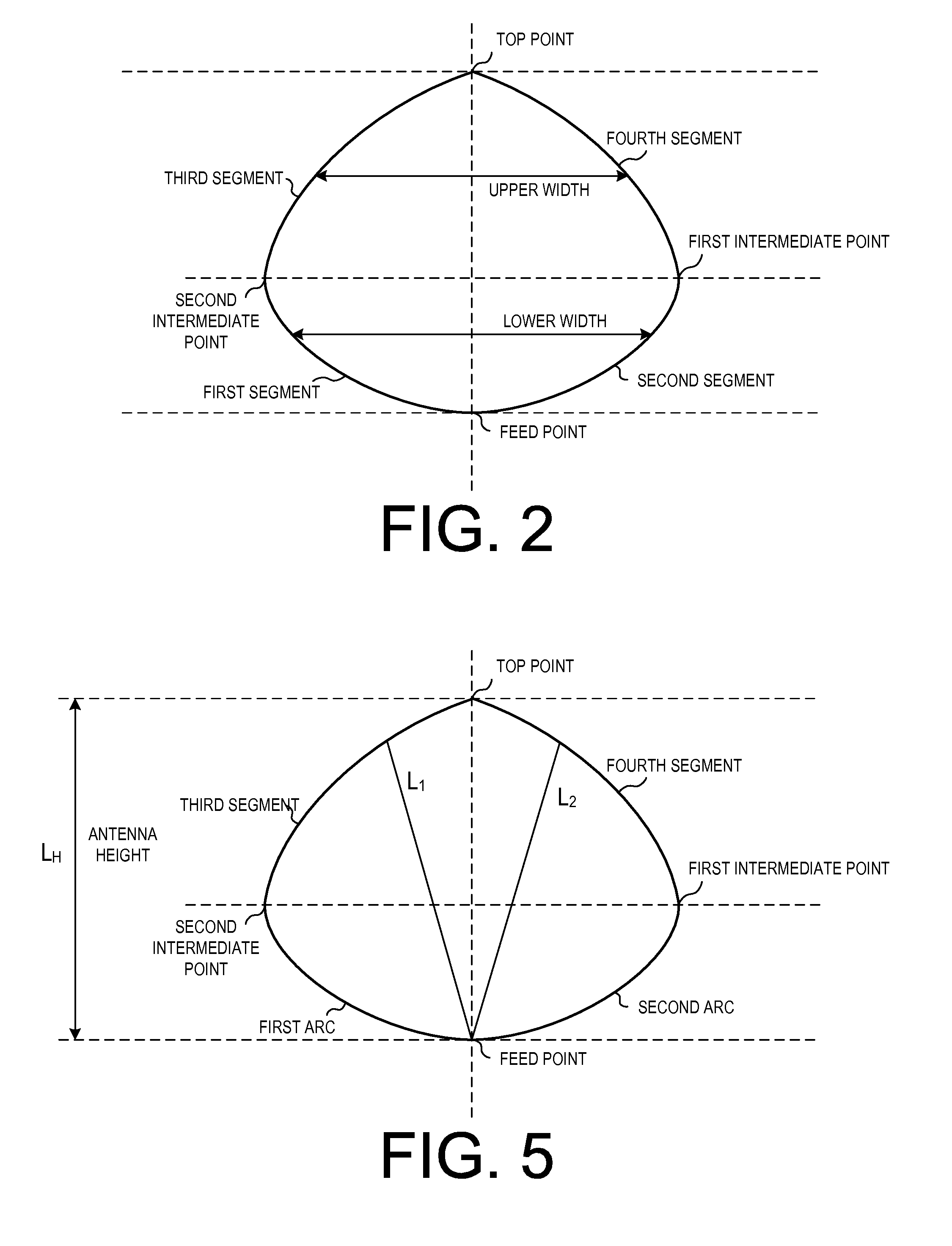
[0009]In view of the foregoing, there exists a need in the art, and accordingly, it is an object of this invention to provide an electrically small, directional, low dispersion, wide bandwidth, low cost antenna that has an unbalanced feed where transmit and or receiving circuits can be integrated onto the same substrate to eliminate transmission line losses, dispersion, and ringing.

Problems solved by technology

As recognized by the present inventor, none of the above UWB antennas, however, provide high bandwidth, directional, and non-dispersive characteristics in an electrically small size and in a cost-effective manner.
That is, these antennas are expensive to manufacture and mass produce.
Non-dispersive antennas have particular application in low cost radio and radar systems that require high spatial resolution and cannot afford the costs associated with adding inverse filtering components to mitigate the phase distortion.
Another common problem as presently recognized by the inventor, is that most UWB antennas require balanced (i.e., differential) sources and loads.
The balanced feed, results in additional manufacturing costs and reduced performance.
For example, baluns raise the cost, attenuate the signal, limit the bandwidth, and often skew the beam pattern of balanced antennas.
Another problem with traditional antennas is that it is difficult to control system ringing.
From a practical standpoint, this ringing problem is always present because the antenna impedance, and the transceiver impedance are never perfectly matched with the transmission line impedance.
The resulting back-and-forth echoes thereby degrade the performance of UWB systems.
Ringing is particularly problematic in time domain duplex communication systems and in radar systems because echoes from the high power transmitter can cause long lasting echoes, lasting long enough to cover up the micro-watt signals that must be received nearly immediately after the transmitter finishes sending a burst of energy.
Both of these phenomena cause distortion of the pulses flowing through the transmission line.

Method used


Image

  • Electrically small octave bandwidth non-dispersive uni-directional antenna
  • Electrically small octave bandwidth non-dispersive uni-directional antenna
  • Electrically small octave bandwidth non-dispersive uni-directional antenna

Examples


Embodiment Construction

[0034]The instant disclosure is provided to further explain in an enabling fashion the best modes of performing one or more embodiments of the present invention. The disclosure is further offered to enhance an understanding and appreciation for the inventive principles and advantages thereof, rather than to limit in any manner the invention. The invention is defined solely by the appended claims including any amendments made during the pendency of this application and all equivalents of those claims as issued.

[0035]It is further understood that the use of relational terms such as first and second, and the like, if any, are used solely to distinguish one from another entity, item, or action without necessarily requiring or implying any actual such relationship or order between such entities, items or actions. It is noted that some embodiments may include a plurality of processes or steps, which can be performed in any order, unless expressly and necessarily limited to a particular or...


PUM


Abstract

An electrically small antenna is disclosed that is directional, has over an octave bandwidth, is non-dispersive, is inexpensive to mass produce, and allows transmitter and receiver electronic components to be integrated into the antenna.

Description

CROSS-REFERENCE TO RELATED APPLICATIONS[0001]This application relies for priority on and claims the benefit of U.S. provisional patent application Ser. No. 61 / 425,212, entitled “ELECTRICALLY SMALL OCTAVE BANDWIDTH NON-DISPERSIVE UNI-DIRECTIONAL ANTENNA,” which was filed on Dec. 20, 2010, the contents of which are hereby incorporated by reference in their entirety.FIELD OF THE INVENTION[0002]The present invention relates generally to antenna apparatuses and systems, and more particularly, to non-dispersive, electrically small wide relative bandwidth antennas.BACKGROUND OF THE INVENTION[0003]With respect to the antenna of radar and wide bandwidth communications systems, key antenna characteristics include the size (in wavelengths at the lowest frequency), the beam pattern as a function of frequency, the efficiency versus frequency, the input impedance versus frequency, and the dispersion. Typically, antennas operate with only a few percent bandwidth, where bandwidth is defined to be t...

Claims


Application Information

Patent Timeline
Patent Type & Authority Applications(United States)
IPC IPC(8): H01Q9/04
CPCH01Q9/28H01Q13/085H01Q9/40
Inventor MCCORKLE, JOHN W.
Owner MCCORKLE JOHN W
Why Eureka
Try Eureka