Dielectrically-loaded antenna

a technology of dielectric loading and antennas, applied in the direction of antennas, non-resonant long antennas, radiating element structural forms, etc., can solve the problem of insufficient bandwidth for many applications

Inactive Publication Date: 2005-07-05
SARANTEL LTD
View PDF21 Cites 96 Cited by
  • Summary
  • Abstract
  • Description
  • Claims
  • Application Information

AI Technical Summary

Benefits of technology

[0013]Using groups of two elements with non-parallel edges it is possible to achieve a fractional bandwidth in excess of 3% at an insertion lo...

Problems solved by technology

Whilst this antenna has advantageous properties in terms of isolation from the structure on which it is mounted, its radiation pattern, and specific absorption ratio (SAR) performanc...

Method used


Image

  • Dielectrically-loaded antenna
  • Dielectrically-loaded antenna
  • Dielectrically-loaded antenna

Examples


Embodiment Construction

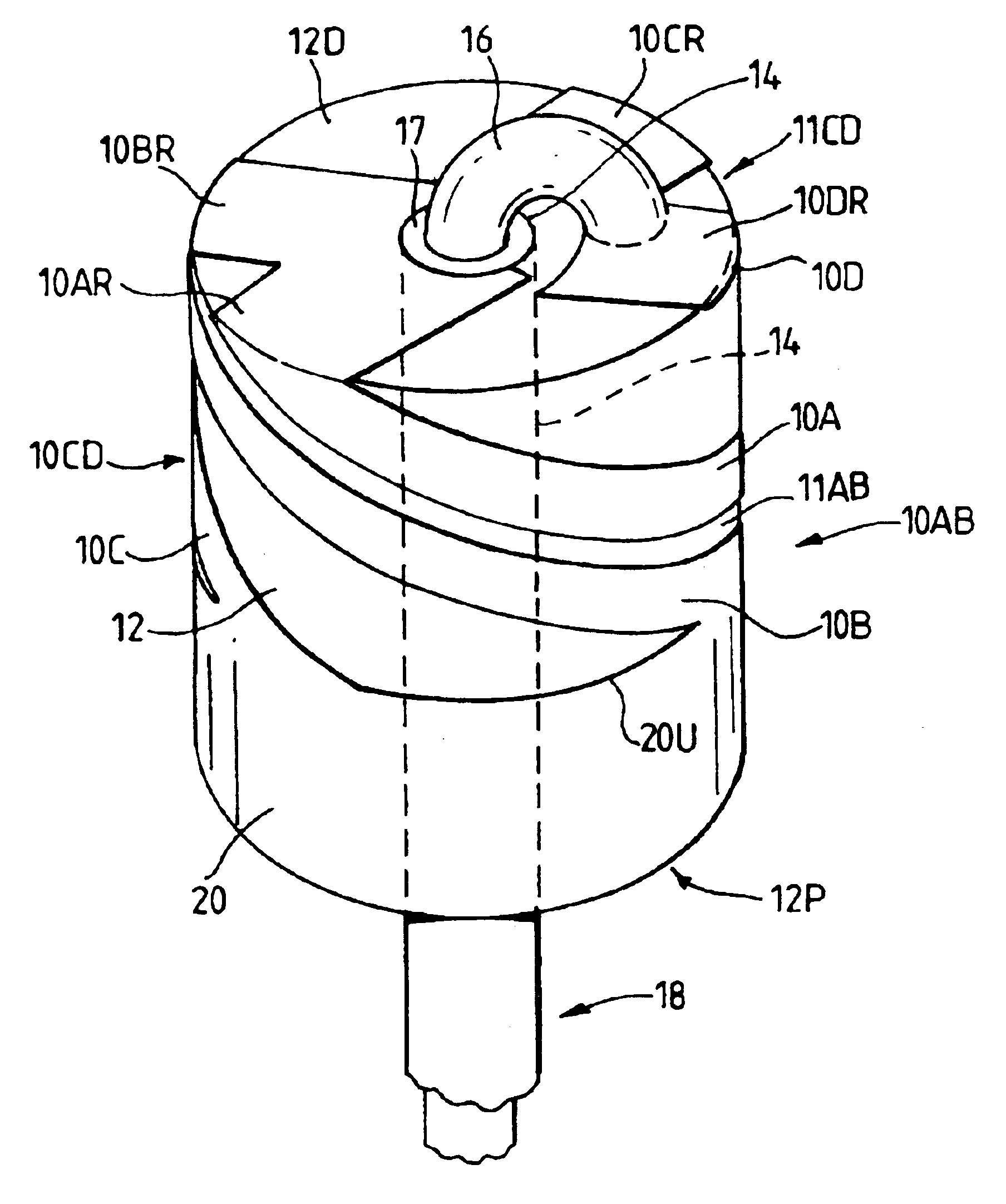
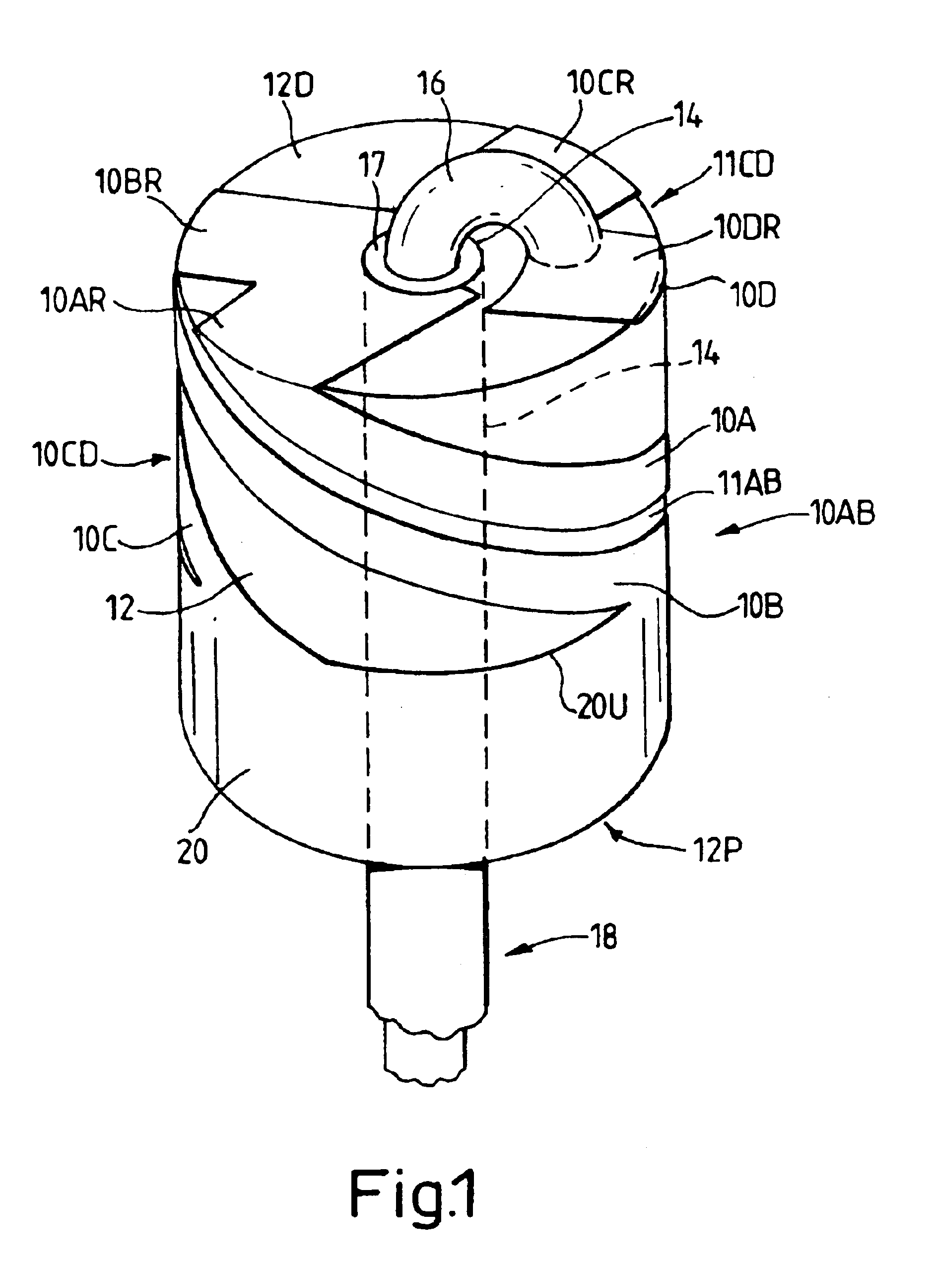
[0023]Referring to FIG. 1, an antenna of a construction similar to that shown in British Patent Application No. 2351850A has an antenna element structure comprising a pair of laterally opposed groups 10AB, 10CD of elongate radiating antenna elements 10AB, 10CD. The term “radiating” is used in this specification to describe antenna elements which, when the antenna is connected to a source of radio frequency energy, radiate energy into the space around the antenna. It will be understood that, in the context of an antenna for receiving radio frequency signals, the term “radiating elements” refers to elements which couple energy from the space surrounding the antenna to the conductors of the antenna for feeding to a receiver.

[0024]Each group of elements comprises, in this embodiment, two coextensive, mutually adjacent and generally parallel elongate antenna elements 10A, 10B, 10C, 10D which are disposed on the outer cylindrical surface of an antenna core 12 made of a ceramic dielectric ...


PUM


Abstract

A dielectrically-loaded loop antenna with a cylindrical dielectric core, a feeder structure passing axially through the core, a sleeve balun encircling one end portion of the core and helical antenna elements extending from a feed connection with the feeder structure at the other end of the core to the rim of the balun. The antenna elements are arranged as a pair of laterally opposed groups of conductive elongate helical elements each having at least first and second conductive elements of different electrical lengths to form a plurality of looped conductive paths. By forming at least one of the conductive elements in each group as a conductive strip with one or both edges meandered, such that the edges of the strip are non-parallel and have different electrical lengths, additional modes of resonance arc created, yielding an improvement in bandwidth.

Description

CROSS-REFERENCE TO RELATED APPLICATION[0001]This application is related to, and claims a benefit of priority under one or more of 35 U.S.C. 119(a)-119(d) from copending foreign patent application United Kingdom 0307251.9, filed Mar. 28, 2003, the entire contents of which are hereby expressly incorporated herein by reference for all purposes.FIELD OF THE INVENTION[0002]This invention relates to a dielectrically-loaded antenna for operation at frequencies in excess of 200 MHz, and in particular to a loop antenna having a plurality of resonant frequencies within a band of operation.BACKGROUND OF THE INVENTION[0003]A dielectrically-loaded loop antenna is disclosed in British Patent Application No. 2309592A. Whilst this antenna has advantageous properties in terms of isolation from the structure on which it is mounted, its radiation pattern, and specific absorption ratio (SAR) performance when used on, for instance, a mobile telephone close to the user's head, it suffers from the generic...

Claims


Application Information

Patent Timeline
IPC IPC(8): H01Q5/00H01Q11/08H01Q7/00H01Q11/00H01Q5/10H01Q5/371
CPCH01Q7/00H01Q5/371H01Q11/08H01Q5/20H01Q1/36H01Q1/38H01Q5/00
Inventor LEISTEN, OLIVER PAUL
Owner SARANTEL LTD
Why Eureka
Try Eureka