
Servo writer

a servo writer and writer technology, applied in the direction of maintaining head carrier alignment, mechanical tension control of carrier, instruments, etc., can solve the problem of high density of magnetic tape, head to completely trace data tracks, and limit only relying on machine accuracy of running device of magnetic tape, so as to prevent errors due to servo signals

Active Publication Date: 2005-07-05
FUJIFILM HLDG CORP +1
View PDF3 Cites 3 Cited by
  • Summary
  • Abstract
  • Description
  • Claims
  • Application Information

AI Technical Summary

Benefits of technology

[0017]According to such the constitution, a head of the tape drive can follow the servo signals and when recording / reproducing data in the tape drive, errors due to the distortion of the servo signals can be prevented.

Problems solved by technology

A problem to make high density of the magnetic tape exists in how to increase recording density of information per unit area.
Therefore, for example, although making a width of a single data track in which data is written as small as possible in a tape width direction, thereby mag a number of data tracks more (improvement of line density), and a substantial increase of a recording capacity is intended, there exists a limit only relying on machine accuracy of running device of a magnetic tape because it becomes difficult for a reproduce head to completely trace the data tracks when reproducing recorded signals in case of making the width of the data tracks small in the tape width direction.
In addition, although the magnetic tape vibration is due to the feedback control, an inconveniency occurs in some cases on the contrary if small deviation in the servo signals written on the magnetic tape occurs by early performing the feedback control of the tape tension.
However, when the servo signals are written on the magnetic tape with a drastic timing error (change) which the magnetic head cannot follow, the magnetic head cannot always operate same in reproducing data and recording data and it causes an off-track (derailing of the reproduce head from a data track)

Method used


Image

  • Servo writer
  • Servo writer
  • Servo writer

Examples


Embodiment Construction

[0022]Hereinafter, one of embodiments of the present invention will be described in detail, referring to drawings as needed.

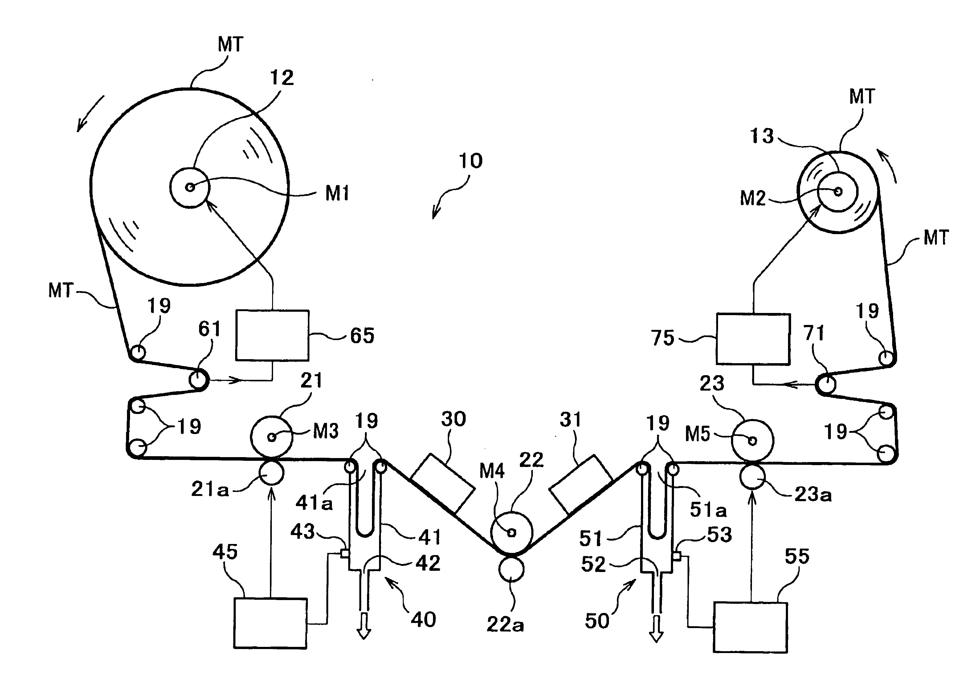
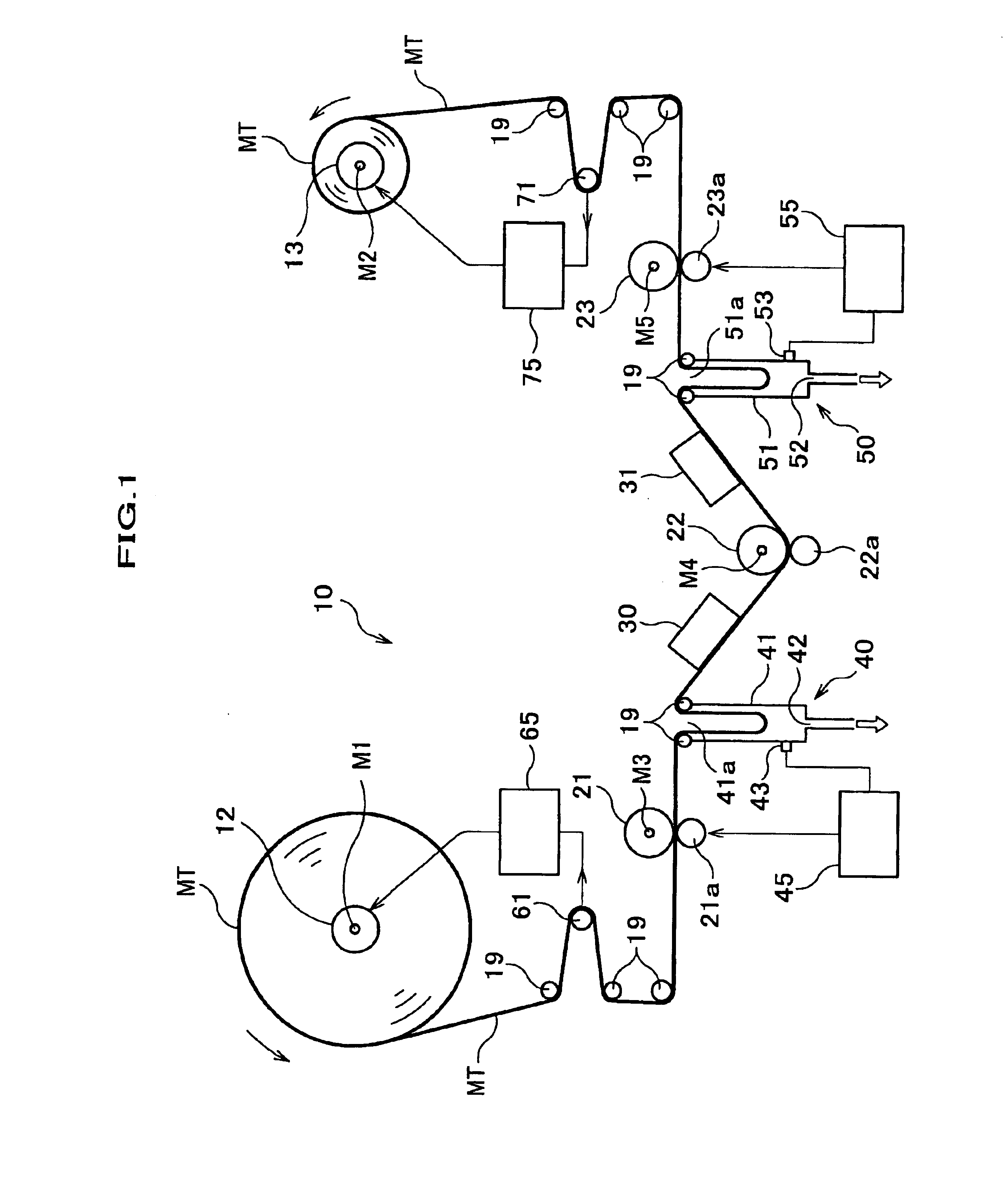
[0023]As shown in FIG. 1, a servo writer 10 is equipment to pay off a magnetic tape MT from a pay-off reel 12 provided at an upstream side of a write head 30, guide a running direction of the magnetic tape MT by many guide rollers 19, and wind the tape MT on a winding reel 13 provided at a downstream side of the write head 30 after writing servo track signals (hereinafter referred to as servo signals) with the write head 30.

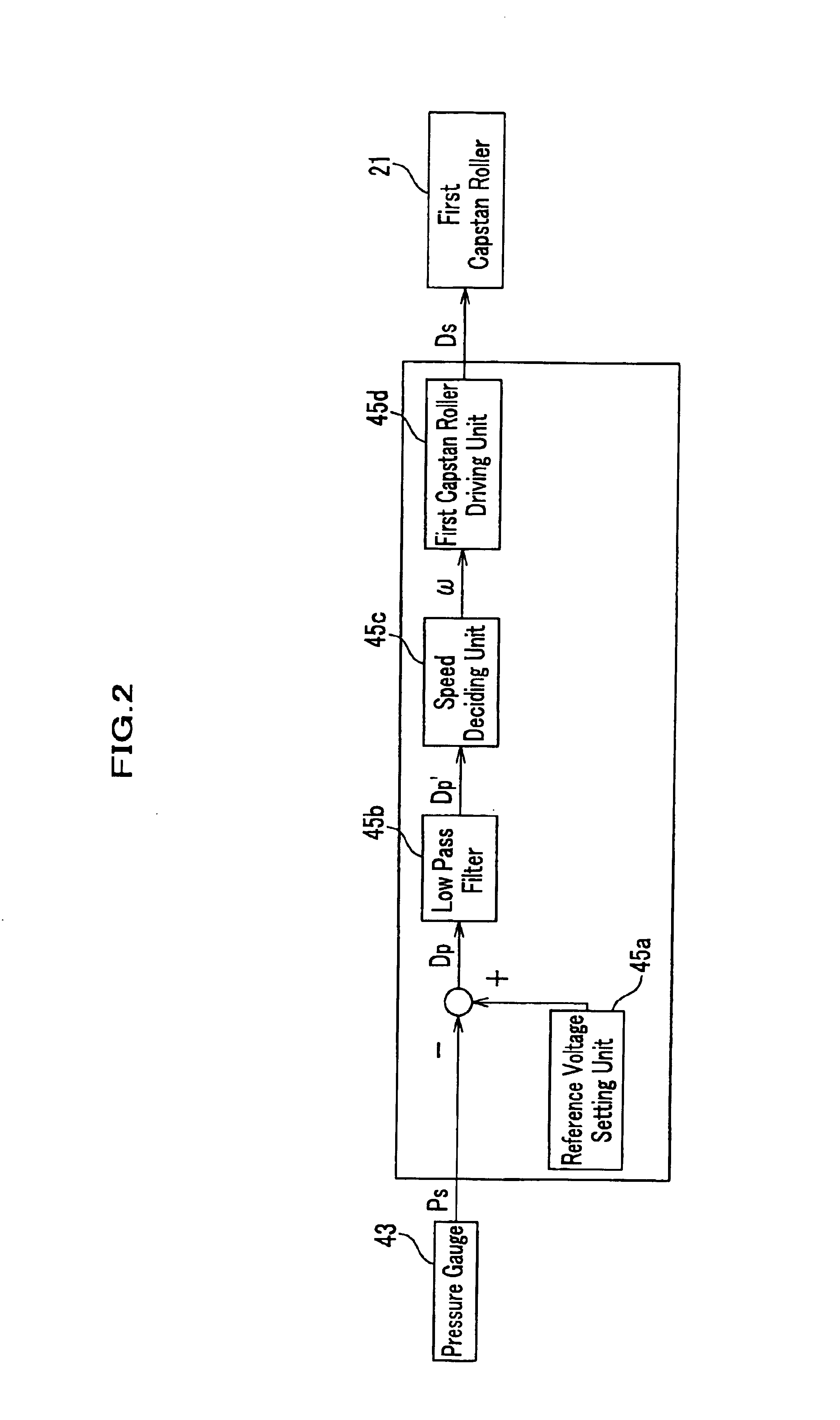
[0024]At an upstream side of the write head 30 is provided a first capstan roller 21 and at a downstream side is provided a second capstan roller 22. Between the first capstan roller 21 and write head 30 is provided a first tension detecting device 40 adjusting tension of the magnetic tape MT. The first tension detecting device 40 corresponds to a tension detect means in claims of the invention. In addition, the first capstan roller 21 corre...


PUM


Abstract

A servo writer which writes a servo mend on a tape by the write head is characterized by being equipped with a pay-off side motor paying off the tape from tie payoff reel by rotating the pay-off reel; a winding side motor winding the tape on the winding reel by rotating the winding reel; a first capstan roller and second capstan roller which are provided at an upstream side and down stream side of the write head, respectively, and by rotating the capstan rollers, run the tape in a state pinched between respective pinch rollers and the capstan rollers; a first tension detector which is provided between the first capstan roller and second capstan roller and detects running tape tension; and a capstan roller controlling unit controlling a rotation speed of the first capstan roller and second capstan roller so that tension detected by the tension detector becomes constant.

Description

FIELD OF THE INVENTION[0001]The present invention relates to a servo writer to write servo signals on a magnetic tape.BACKGROUND OF THE INVENTION[0002]Generally, a magnetic tape is widely used as the tape to record and keep information. A problem to make high density of the magnetic tape exists in how to increase recording density of information per unit area. Therefore, for example, although making a width of a single data track in which data is written as small as possible in a tape width direction, thereby mag a number of data tracks more (improvement of line density), and a substantial increase of a recording capacity is intended, there exists a limit only relying on machine accuracy of running device of a magnetic tape because it becomes difficult for a reproduce head to completely trace the data tracks when reproducing recorded signals in case of making the width of the data tracks small in the tape width direction.[0003]On the other hand, in a recent high-density magnetic tap...

Claims


Application Information

Patent Timeline
IPC IPC(8): G11B15/00G11B15/56G11B15/58G11B5/584G11B5/00G11B15/43G11B15/46
CPCG11B5/584G11B15/56G11B15/58
Inventor IZUMIDA, TAKAHISAHASHIMOTO, AKIHIRO
Owner FUJIFILM HLDG CORP
Learn More