Giant magnetoresistive sensor having selfconsistent demagnetization fields

Inactive Publication Date: 2005-07-05
SEAGATE TECH LLC
View PDF40 Cites 36 Cited by
  • Summary
  • Abstract
  • Description
  • Claims
  • Application Information

AI Technical Summary

Benefits of technology

[0011]The biasing component produces a bias magnetization field that biases both M1 and M2 in a third direction that is transverse to the first and second directions and establishes quiescent bias states for M1 and M2. The magnetizations M1 and M2 are allowed to rotate about their quiescent bias states in response to an applied magnetic field. This rotation produces a GMR effect in the sensor as a function of the rotation of M1 and M2.

Problems solved by technology

This side-reading is a source of noise in the recovered data signal, and a source of cross-talk, a phenomenon where the read-head reads data from two or more adjacent tracks.
Consequently, the effects of side-reading in a read head is a limiting factor on the spacing between adjacent tracks, and hence a limiting factor to increased areal density.
Additionally, the demagnetization fields can push the biased point in the reader transfer curve of the GMR sensor to its non-linear region creating symmetry and stability problems.
For many spin valve sensor designs, the demagnetization fields are a limiting factor to the minimum width of the sensor and thus a limiting factor to the areal density of the data they can reliably read.
Successive flux elements are recorded in opposite magnetic orientation along the track length, so that by limiting the length of the transducing gap to that of a single flux element, two or more successive flux elements are not read simultaneously, which could lead to their cancellation.
This increase in spacing between the top and bottom shield can cause the spin valve to read multiple flux elements thereby resulting in a canceling effect on the read signal.

Method used


Image

  • Giant magnetoresistive sensor having selfconsistent demagnetization fields
  • Giant magnetoresistive sensor having selfconsistent demagnetization fields
  • Giant magnetoresistive sensor having selfconsistent demagnetization fields

Examples


Embodiment Construction

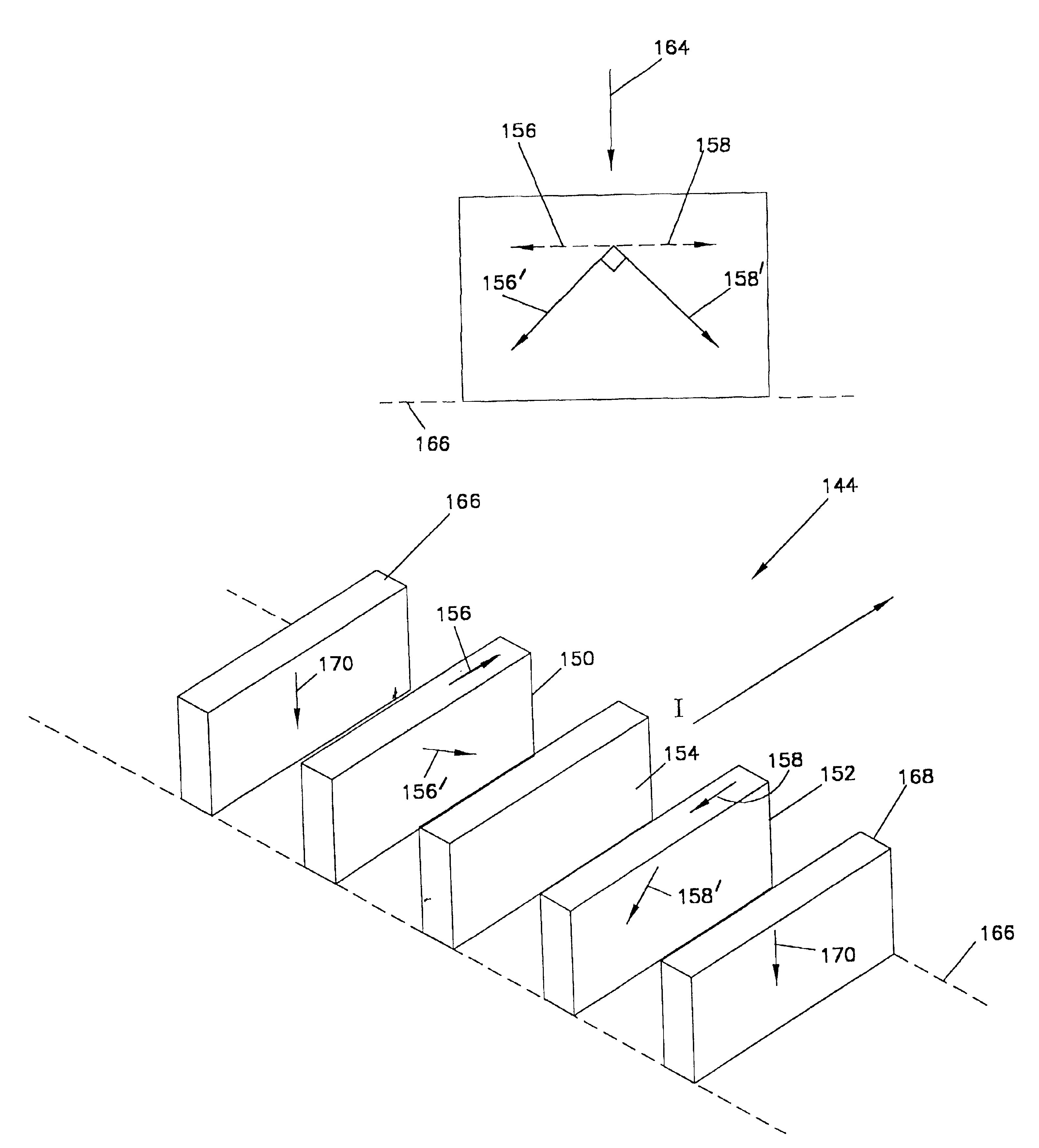
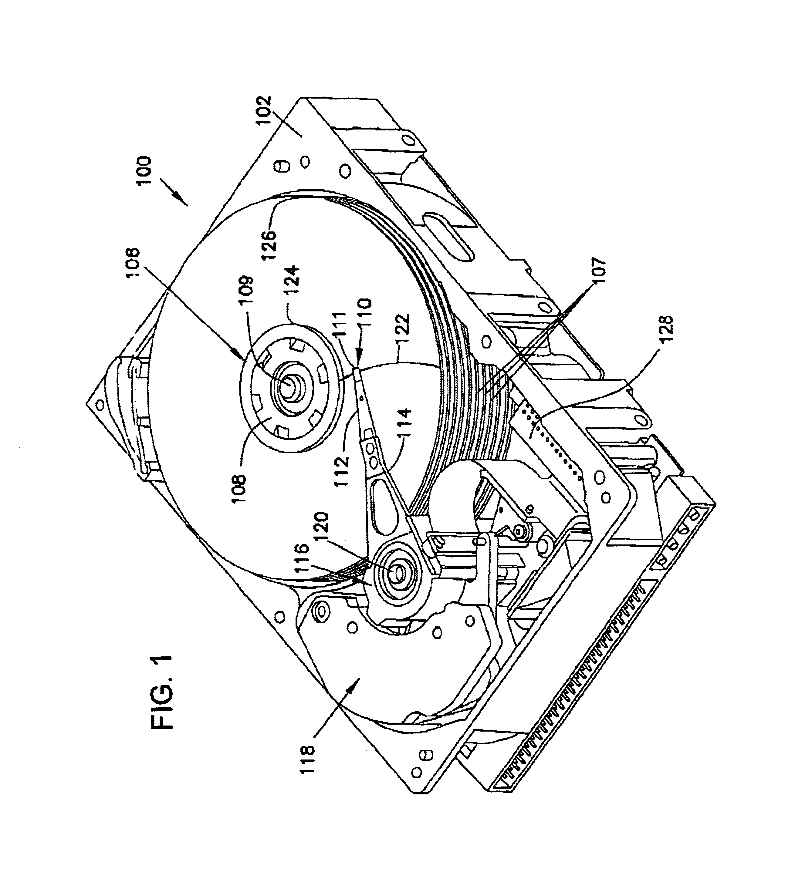
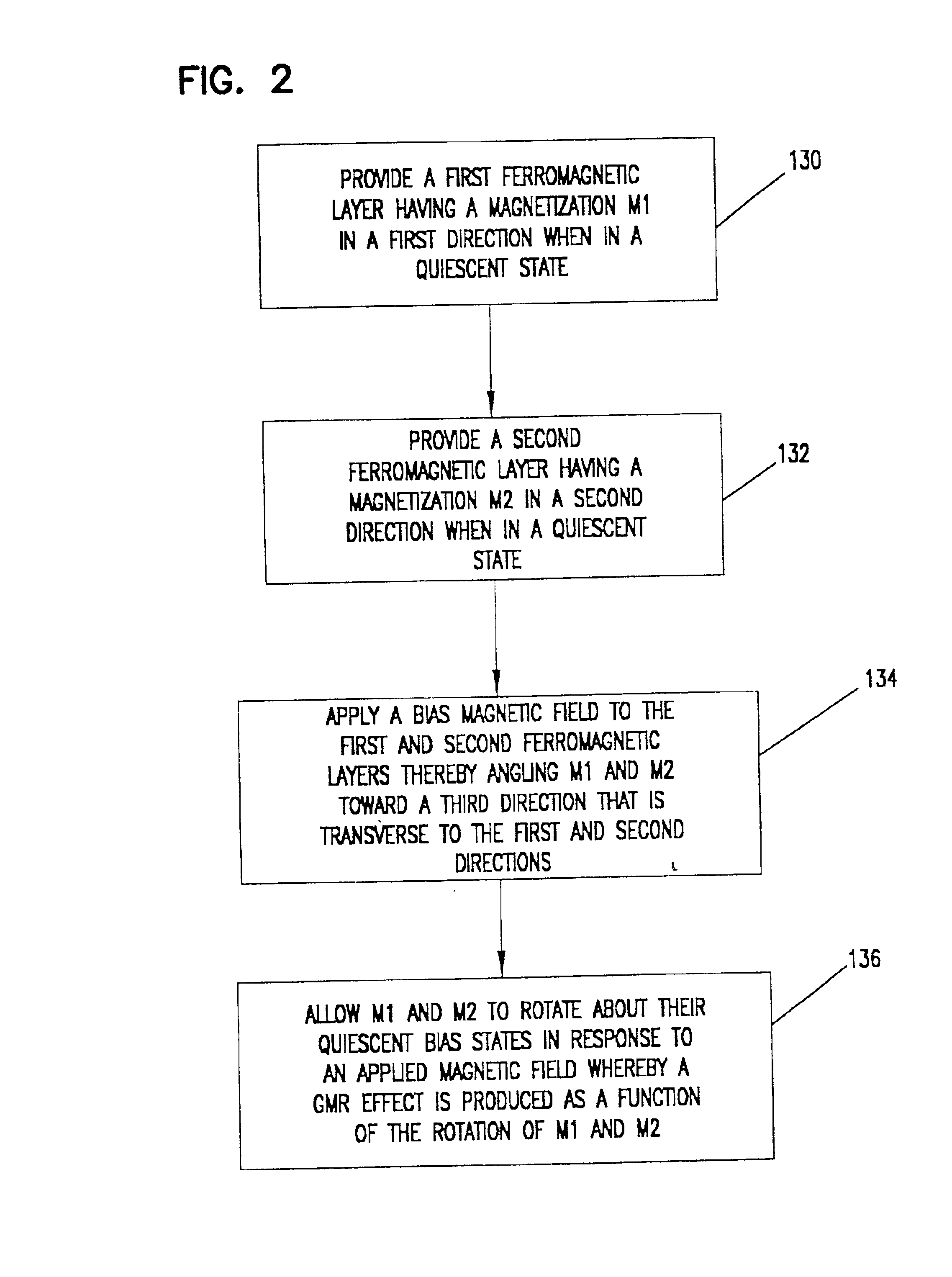
[0021]The present invention relates to magnetoresistive sensors of the giant magnetoresistive (GMR) or spin valve type which are used to read back information from recording media, such as magnetic discs. It is desirable that spin valve sensors be capable of reading high areal density data recordings (on the order of 100 Gb / In2). It is necessary that the spin valve sensor be reduced in size in order to allow it to function with such high areal densities. One cost to the reduction in spin valve sensor size is the increased effect that demagnetization fields play in its operation. In particular, the demagnetization fields that would develop in typical spin valve sensor designs that have been sufficiently reduced in size would undesirably decrease the sensitivity of the spin valve sensor to applied to magnetic fields from the magnetic recording media. However, the present invention converts these demagnetization fields from a detriment into a benefit.

[0022]The spin valve sensor of the ...


PUM


Abstract

The present invention is directed to a spin valve sensor for use in a data storage system, that is adapted to receive a sense current and produce a GMR effect in response to applied magnetic fields. The spin valve sensor includes first and second ferromagnetic free layers, a spacer layer positioned between the first and second ferromagnetic free layers, and a biasing component. The first ferromagnetic free layer has a magnetization (M1) in a first direction, when in a quiescent (non-biased) state. The second ferromagnetic free layer has a magnetization (M2) in a second direction that is anti-parallel to the first direction, when in a quiescent (non biased) state.

Description

CROSS-REFERENCE TO RELATED APPLICATION[0001]This application claims priority to U.S. Provisional Application No. 60 / 233,815 filed Sep. 19, 2000 by Lujun Chen, Jim Giusti and Juan Fernandez-de-Castro, and entitled “NEW MR READER STRUCTURES BASED ON STRAY & DEMAG FIELDS WITH DOWNWARD EXTERNAL FIELD” and is also a continuation of International Application Number PCT / US01 / 13417, filed on Apr. 26, 2001 for “GIANT MAGNETORESISTIVE SENSOR HAVING SELF-CONSISTENT DEMAGNETIZATION FIELDS,” which in turn claims priority to the aforementioned U.S. provisional application.FIELD OF THE INVENTION[0002]The present invention relates to data storage systems. More specifically, the present invention relates to spin valve sensors for use in data storage systems that is adapted to produce the giant magnetoresistive (GMR) effect in response to an applied magnetic field.BACKGROUND OF THE INVENTION[0003]Giant magnetoresistive (GMR) sensors are employed in read heads of magnetic data storage devices to read ...

Claims


Application Information

Patent Timeline
IPC IPC(8): G01R33/06G01R33/09G11B5/39G11B5/00G11B5/02H01L43/08
CPCB82Y10/00B82Y25/00G01R33/093G11B5/02G11B5/3903G11B2005/0008G11B2005/3996
Inventor CHEN, LUJUNGIUSTI, JAMES H.FERNANDEZ-DE-CASTRO, JUAN J.
Owner SEAGATE TECH LLC
Why Eureka
Try Eureka