Communication terminal apparatus and radio reception method

a technology of communication terminal and radio reception, which is applied in the direction of transmission, synchronisation arrangement, wireless communication, etc., can solve the problems of reducing the reliability of path selection and the searcher selecting the wrong path, and achieves accurate path selection, high reliability, and accurate path selection.

Inactive Publication Date: 2005-07-05
PANASONIC CORP
View PDF7 Cites 31 Cited by
  • Summary
  • Abstract
  • Description
  • Claims
  • Application Information

AI Technical Summary

Benefits of technology

[0011]It is an object of the present invention to provide a communication terminal apparatus and radio reception method capable of performing path selection accurately with high reliability even in the case where a base station performs directional controlled transmission.
[0012]It is a subject of the present invention that in a DS-CDMA system in which forwar

Problems solved by technology

Therefore there is a problem that the searcher selects a wrong path when operates using the common control channel signals as references as described above.
On the other hand, when the searcher operates using the tr

Method used


Image

  • Communication terminal apparatus and radio reception method
  • Communication terminal apparatus and radio reception method
  • Communication terminal apparatus and radio reception method

Examples


first embodiment

[0029](First Embodiment)

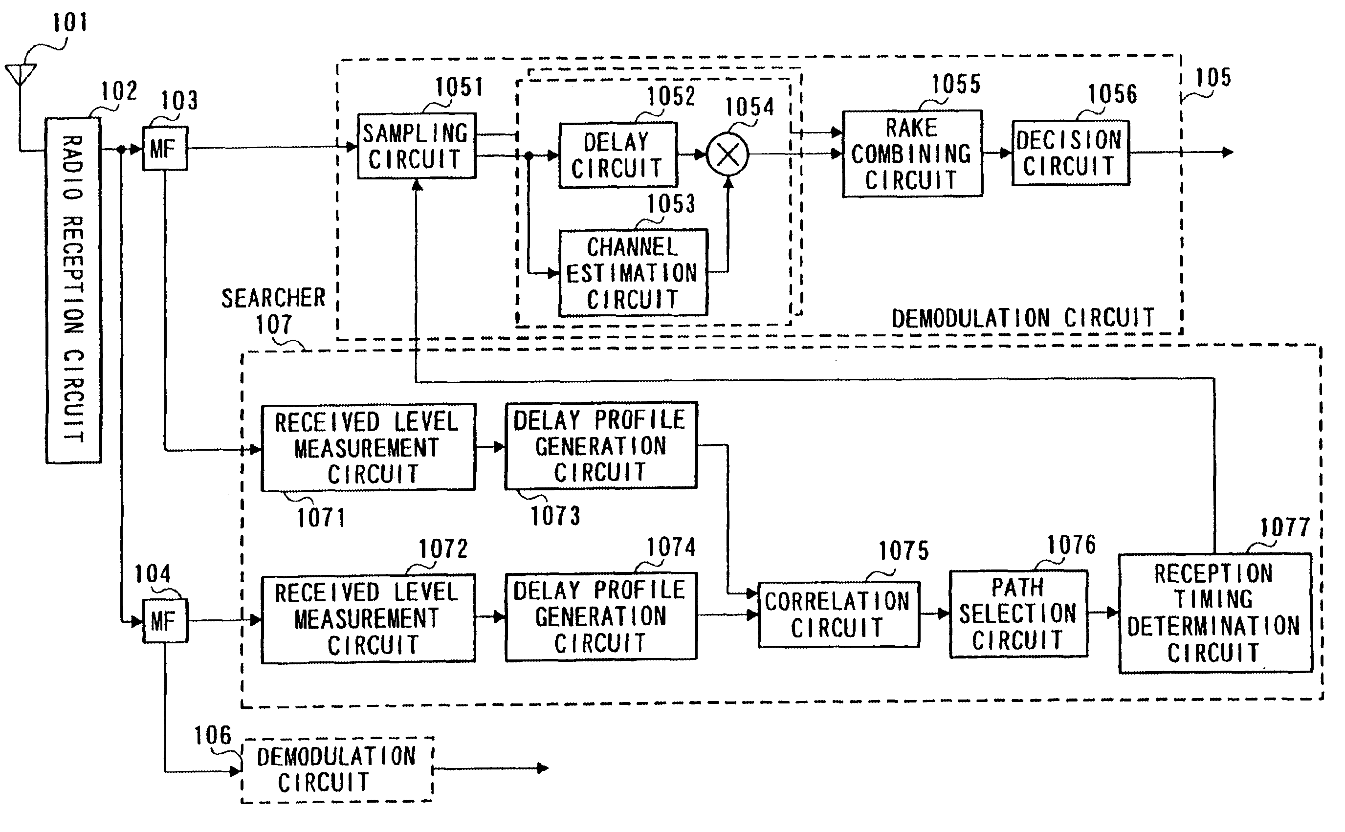
[0030]FIG. 3 is a block diagram illustrating a configuration of a communication terminal apparatus according to the first embodiment of the present invention. Herein it is assumed that dedicated physical channel (DPCH: traffic channel) signals are controlled with a transmission radiation pattern in a forward channel from a base station to a communication terminal. In addition only a reception side is described in the communication terminal apparatus illustrated in FIG. 3.

[0031]A directional controlled signal transmitted from the base station is received in radio reception circuit 102 through antenna 101. Radio reception circuit 102 performs amplification (gain control), downconverting, and A / D conversion on a received signal. A / D converted data is despread in matched filters 103 and 104 with respective spreading codes used in spreading in the base station. Herein, data of the traffic channel (DPCH) is despread in matched filter 103, and data of a common contr...

second embodiment

[0051](Second Embodiment)

[0052]This embodiment explains a case that preliminary selection is performed for paths on which the correlation calculation between the delay profiles is performed.

[0053]FIG. 5 is a block diagram illustrating a configuration of a communication terminal apparatus according to the second embodiment of the present invention. In addition, in the communication terminal apparatus illustrated in FIG. 5, the same sections as in the communication terminal apparatus illustrated in FIG. 3 are given the same marks as in FIG. 3 to omit specific explanations thereof.

[0054]In the communication terminal apparatus according to this embodiment, searcher 301 has received level measurement circuits 3011 and 3012 that measure received levels of despread data, delay profile generation circuits 3013 and 3014 that generate respective delay profiles of the channels based on respective measured results of the received levels, path candidate selection circuit 3015 that selects path c...

third embodiment

[0066](Third Embodiment)

[0067]In the second embodiment, it is assumed that a channel on which the path candidate selection is performed is the traffic channel. However, there is considered a condition that the traffic channel is not appropriate as a channel on which the path candidate selection is performed. For example, in the case where a received signal in the traffic channel has a low SIR due to the transmit power control, or the received level per one path is extremely low due to a large number of multipaths, it is difficult to perform the preliminarily selection with high reliability. Therefore this embodiment explains a case that a channel on which the path preliminary selection is performed is switched.

[0068]FIG. 6 is a block diagram illustrating a configuration of a communication terminal apparatus according to the third embodiment of the present invention. In addition, in the communication terminal apparatus illustrated in FIG. 6, the same sections as in the communication ...


PUM


Abstract

Received level measurement circuit 1071 performs received level measurement using input despread traffic channel data. Received level measurement circuit 1072 performs received level measurement using input despread common control channel data. These received levels are respectively output from received level measurement circuits 1071 and 1072 to correlation circuit 1075. Correlation circuit 175 first performs correlation calculation between paths in respective profiles of the traffic channel and common control channel each generated based on respective received level. Based on the result of the correlation calculation, path selection is performed to determine a reception timing.

Description

BACKGROUND OF THE INVENTION[0001]1. Field of the Invention[0002]The present invention relates to a communication terminal apparatus and radio reception method in a digital radio communication system, and more particularly, to a communication terminal apparatus and radio reception method in a Direct Sequence-Code Division Multiple Access system in which forward transmission directional control is applied using a smart antenna and adaptive array antenna.[0003]2. Description of the Related Art[0004]Conventionally in the case where traffic channel signals and common control channel signals are transmitted with the same transmission method (both with omnidirectional), dedicated physical channel (traffic channel) signals are controlled with a very limit received level (Eb / NO or SIR) providing a required quality by transmit power control to improve the spectral efficiency.[0005]On the contrary, with respect to the common control channel signals, in order to enable all communication termina...

Claims


Application Information

Patent Timeline
IPC IPC(8): H04B1/707H04B1/40H04B1/7113H04B1/7117
CPCH04B1/709H04B1/7113H04W40/12H04W56/00
Inventor MIYA, KAZUYUKIIMAIZUMI, SATOSHI
Owner PANASONIC CORP
Why Eureka
Try Eureka