Heat exchanger tube support structure

a technology of heat exchanger tube and support structure, which is applied in the direction of indirect heat exchangers, nuclear elements, lighting and heating apparatus, etc., can solve the problems of high cost of corrective actions such as power derating, chemical cleaning or water slap, and increase the secondary water level in the downcomer. , to achieve the effect of reducing local turbulence and reducing pressure drop

Inactive Publication Date: 2005-07-05
BWXT CANADA
View PDF29 Cites 23 Cited by
  • Summary
  • Abstract
  • Description
  • Claims
  • Application Information

AI Technical Summary

Benefits of technology

[0008]The problems associated with the prior art tube support plates are largely overcome by the present invention which resorts to a stronger more corrosive resistant plate material such as stainless steel and by formi...

Problems solved by technology

These deposits block the bights formed between protruding members and thus cause undesirable increases in pressure drop which will in turn result in an increase in the secondary water level in the downcomer.
If corrective actions are not taken, the rising water level could potentially flood the steam ble...

Method used


Image

  • Heat exchanger tube support structure
  • Heat exchanger tube support structure
  • Heat exchanger tube support structure

Examples


Embodiment Construction

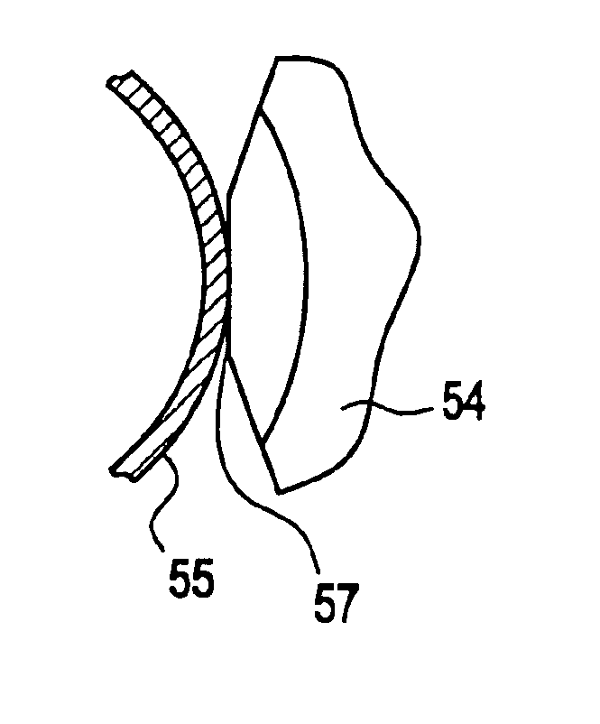
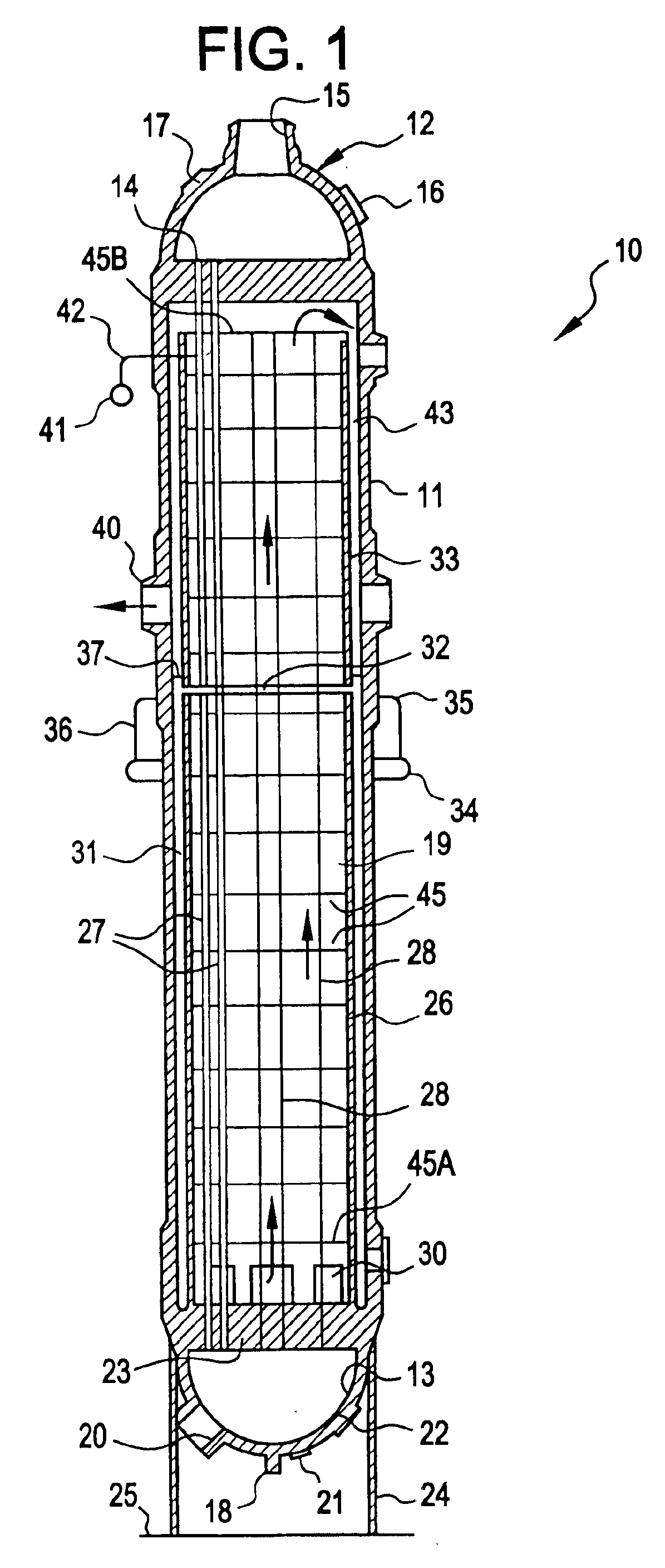
[0022]The present invention is described in connection with a once-through steam generator for a nuclear power plant, although these principles are generally applicable to shell and tube heat exchangers in any number of diverse fields of activities. Thus, as shown in FIG. 1 for the purpose of illustration, a once-through steam generator unit 10 comprising a vertically elongated cylindrical pressure vessel or shell 11 closed at its opposite ends by an upper head member 12 and a lower head member 13.

[0023]The upper head includes an upper tube sheet 14, a primary coolant inlet 15, a manway 16 and a handhole 17. The manway 16 and the handhole 17 are used for inspection and repair during times when the vapor generator unit 10 is not in operation. The lower head 13 includes drain 18, a coolant outlet 20, a handhole 21, a manway 22 and a lower tube sheet 23.

[0024]The vapor generator 10 is supported on a conical or cylindrical skirt 24 which engages the outer surface of the lower head 13 in...


PUM


Abstract

A support plate for retaining tube array spacing within a heat exchanger tube and shell structure. The support plate having a plurality of individual tube receiving apertures formed therein. Each aperture has at least three inwardly protruding members and bights are formed therebetween when the tube associated therewith is lodged in place to establish secondary fluid flow through the support plate. The inwardly protruding members terminate in flat lands that restrain but do not all contact the outer surface of the respective tube. These flat lands minimize fretting wear and eliminate potential gouging of the outer wall of the tube. The plate wall forming each aperture has an hourglass configuration which, inter alia, reduces pressure drop, turbulence and local deposition of magnetite and other particulates on the support plates.

Description

CROSS REFERENCE TO RELATED APPLICATIONS[0001]This application is divisional application of application U.S. Ser. No. 10 / 285,178 filed Oct. 31, 2002 now U.S. Pat. No. 6,810,101 which is hereby incorporated herein by reference. U.S. Ser. No. 10 / 285,178 is a continuation of U.S. Pat. No. 6,498,827 filed on Nov. 1, 1999 and issued on Dec. 24, 2002 which is hereby incorporated by reference.FIELD AND BACKGROUND OF THE INVENTION[0002]The invention relates generally to heat exchanger construction and more particularly to support plates for retaining tube array spacing within the heat exchanger.DESCRIPTION OF THE PRIOR ART[0003]The pressurized water vapor generators or heat exchangers, associated with nuclear power stations and which transfer the reactor-produced heat from the primary coolant to the secondary coolant that drives the plant turbines may be as long as 75 feet and have an outside diameter of about 12 feet. Within one of these heat exchangers, straight tubes through which the pri...

Claims


Application Information

Patent Timeline
IPC IPC(8): G21C15/00G21C9/00F22B37/20F22B37/66
CPCF22B37/205F22B37/66
Inventor KLARNER, RICHARD G.
Owner BWXT CANADA
Why Eureka
Try Eureka