Parametric audio amplifier system

a technology of audio amplifiers and amplifiers, applied in the direction of magnetic restriction transducers, transducer details, electrical transducers, etc., can solve the problems of significant increase in the size and cost of the system, significant increase in the cost and complexity of the installation, and problematic use of high-voltage connections in parametric audio amplifier systems

Inactive Publication Date: 2005-07-05
POMPEI FRANK JOSEPH
View PDF4 Cites 59 Cited by
  • Summary
  • Abstract
  • Description
  • Claims
  • Application Information

AI Technical Summary

Benefits of technology

[0008]A smaller, less expensive, parametric audio amplifier system is provided that is configured to be conformable to cable routing requirements that are no more stringent than that of conventional loudspeaker systems. The benefits of the presently disclosed amplifier system are achieved by configuring the system so that connections to an acoustic transducer assembly included therein carry only low voltage signals, and by disposing in the acoustic transducer assembly components required for generating high voltage signals to bias and / or drive an acoustic transducer.

Problems solved by technology

One drawback of the conventional parametric audio amplifier system is that the acoustic transducer included therein is typically driven by the driver amplifier with a high voltage signal, which may be on the order of hundreds of volts.
However, the use of high voltage connections in parametric audio amplifier systems can be problematic because such connections typically comprise specialized high voltage cables and / or connectors, which can significantly increase the size and cost of the system.
As a result, special considerations must often be made when installing high voltage cabling for parametric audio amplifier systems, which can significantly increase the cost and complexity of the installation.

Method used


Image

  • Parametric audio amplifier system
  • Parametric audio amplifier system
  • Parametric audio amplifier system

Examples


Embodiment Construction

[0016]U.S. Provisional Patent Application No. 60 / 197,933 filed Apr. 17, 2000 is incorporated herein by reference.

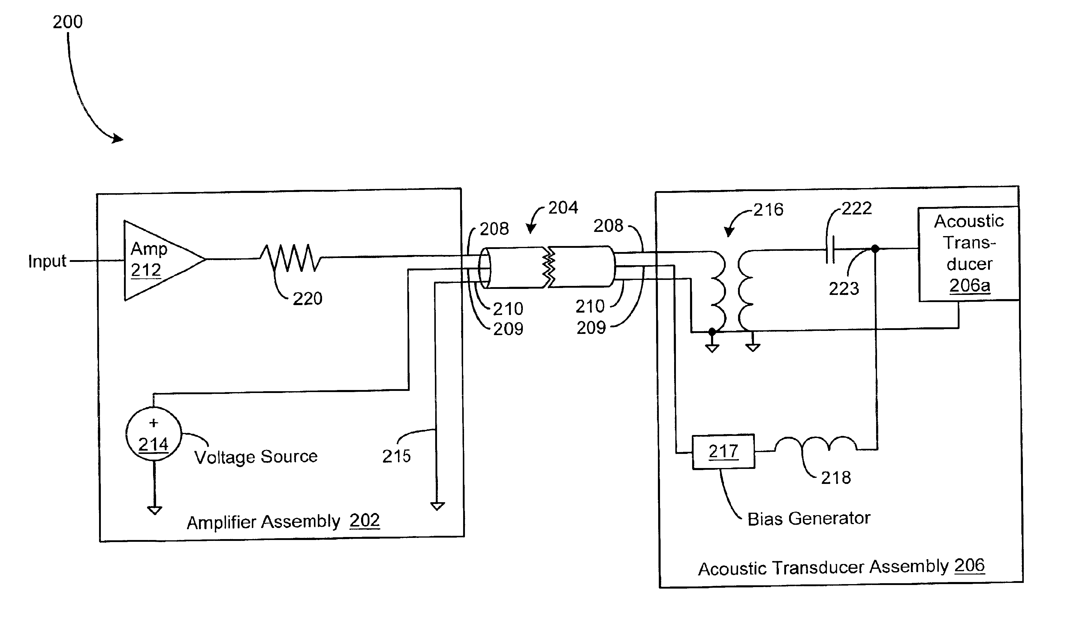
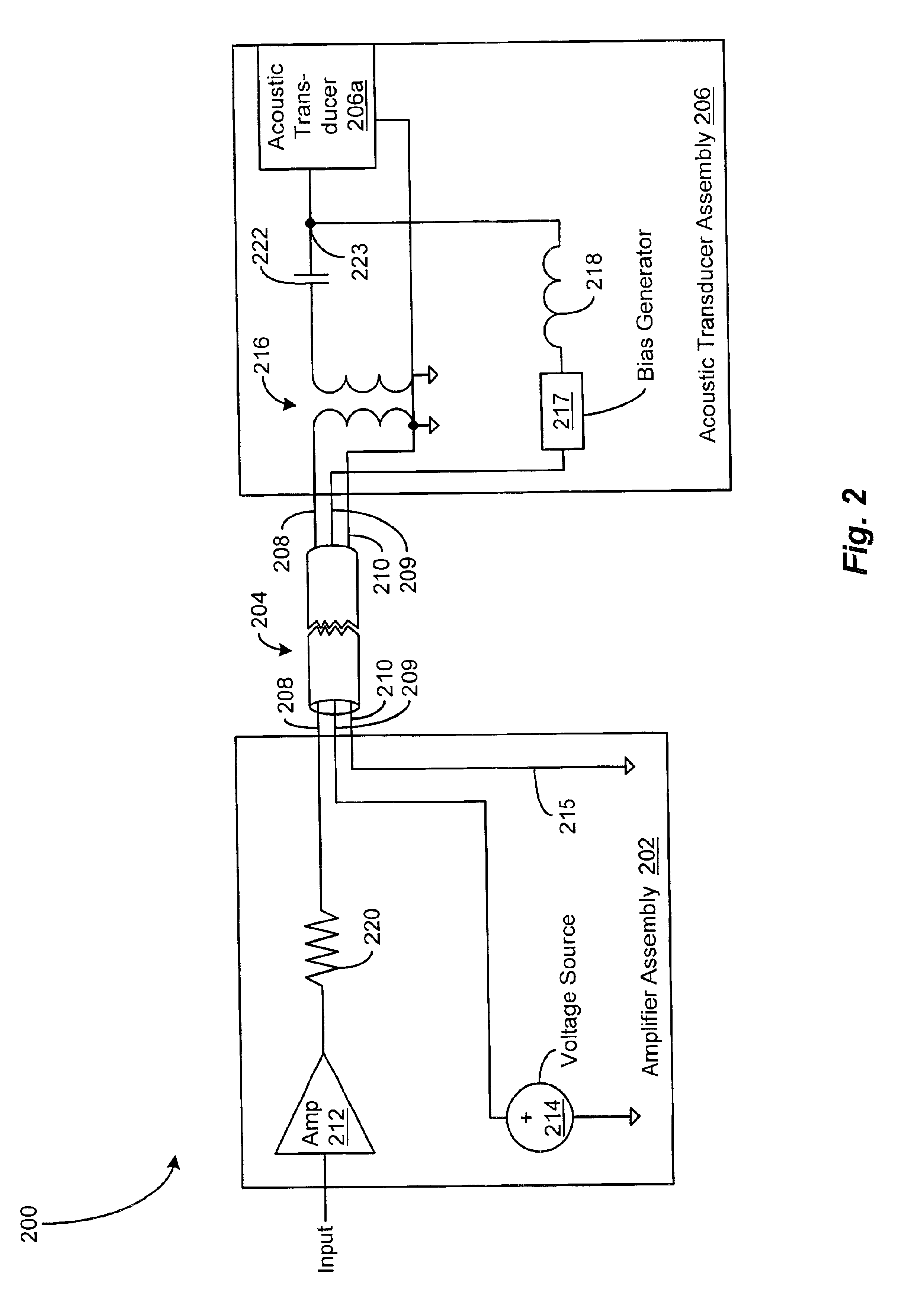
[0017]A parametric audio amplifier system is disclosed that is reduced in size, less expensive, and conformable to cable routing requirements that are no more stringent than that of conventional loudspeaker systems. The presently disclosed amplifier system achieves such benefits by providing a low voltage connection to an acoustic transducer assembly, and by disposing in the acoustic transducer assembly those components required to generate high voltage signals for biasing and / or driving an acoustic transducer.

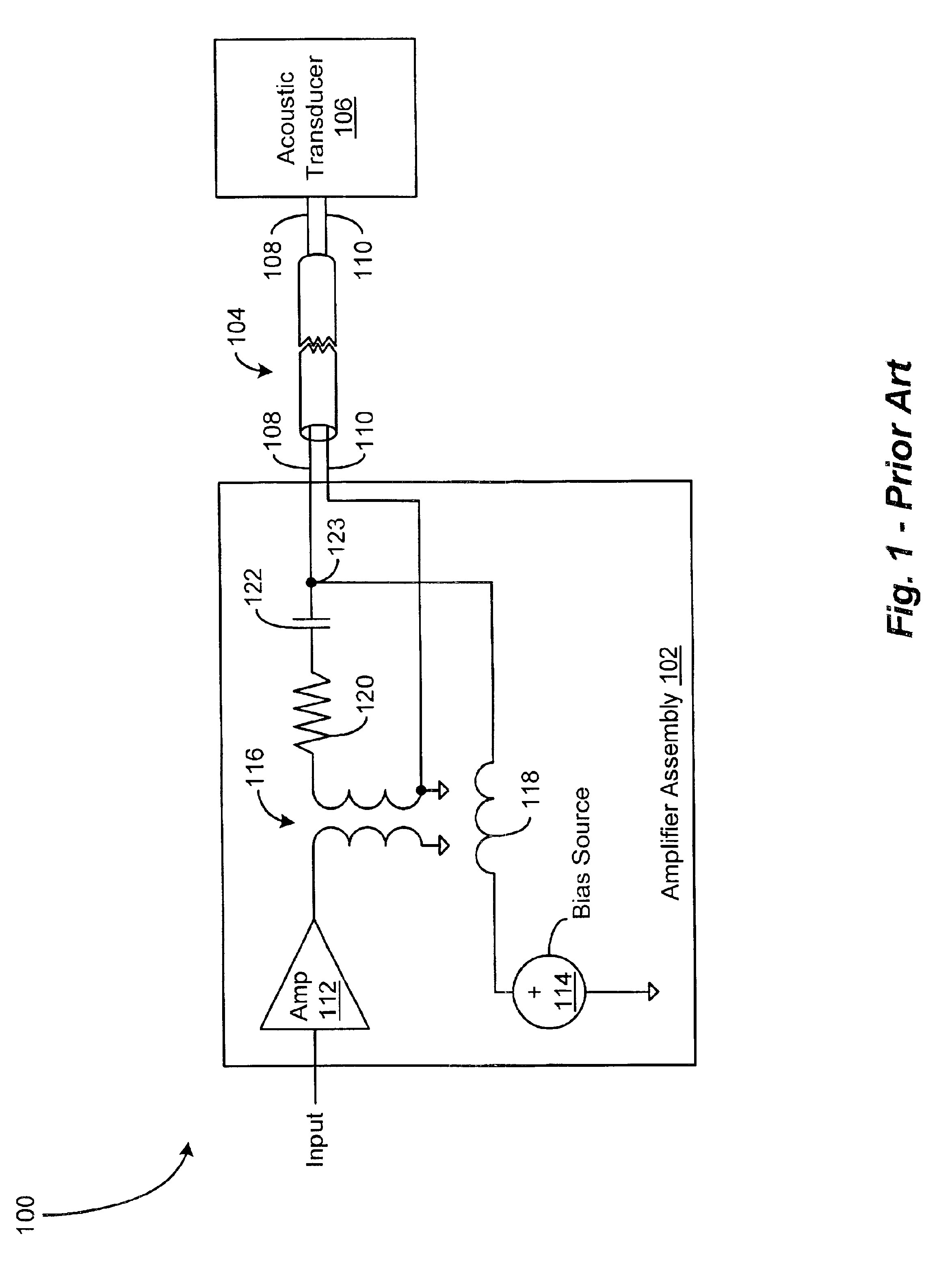
[0018]FIG. 1 depicts a block diagram of a conventional parametric audio amplifier system 100, which includes an amplifier assembly 102, an acoustic transducer 106, and a connection cable 104 for interconnecting the amplifier assembly 102 and the acoustic transducer 106. The amplifier assembly 102 is configured to receive an ultrasonic carrier signal modulated with a...


PUM


Abstract

A smaller, less expensive, parametric audio amplifier system configured to be conformable to cable routing requirements that are no more stringent than that of conventional loudspeaker systems. The parametric audio amplifier system includes an amplifier assembly for amplifying an ultrasonic carrier signal modulated with a processed audio signal, an acoustic transducer assembly for projecting a sonic beam corresponding to the amplified ultrasonic signal through the air to regenerate the audio signal, and a low voltage connection for carrying the amplified ultrasonic signal from the amplifier assembly to the acoustic transducer assembly. The amplifier assembly includes an amplifier for receiving the modulated ultrasonic signal and generating an amplified ultrasonic signal having a low voltage level, and a voltage source for generating a voltage level. The acoustic transducer assembly includes interface circuitry for receiving the amplified ultrasonic signal, and providing a drive signal to an acoustic transducer. The acoustic transducer assembly further includes a bias generator for receiving the voltage level, and providing a bias level to the acoustic transducer.

Description

CROSS REFERENCE TO RELATED APPLICATIONS[0001]This application claims priority of U.S. Provisional Patent Application No. 60 / 197,933 filed Apr. 17, 2000 entitled PARAMETRIC AUDIO AMPLIFIER SYSTEM.STATEMENT REGARDING FEDERALLY SPONSORED RESEARCH OR DEVELOPMENT[0002]N / ABACKGROUND OF THE INVENTION[0003]The present invention relates generally to parametric audio amplifier systems for generating airborne audio signals, and more specifically to a parametric audio amplifier system that employs a low voltage connection between an amplifier assembly and an acoustic transducer assembly.[0004]Parametric audio amplifier systems are known that employ an acoustic transducer for projecting an ultrasonic carrier signal modulated with a processed audio signal through the air for subsequent regeneration of the audio signal along a selected path of projection. A conventional parametric audio amplifier system includes a modulator configured to modulate an ultrasonic carrier signal with a processed audio...

Claims


Application Information

Patent Timeline
Patent Type & Authority Patents(United States)
IPC IPC(8): H04R3/00
CPCH04R3/00H04R2217/03
Inventor POMPEI, FRANK JOSEPH
Owner POMPEI FRANK JOSEPH
Why Eureka
Try Eureka