Method and apparatus for generating gas to a processing chamber

a technology of gas generation and processing chamber, which is applied in lighting and heating apparatus, separation processes, drying machines, etc., can solve the problems of prohibitively expensive gas refinement, difficult handling, and high cost of materials,

Inactive Publication Date: 2005-07-12
APPLIED MATERIALS INC
View PDF197 Cites 99 Cited by
  • Summary
  • Abstract
  • Description
  • Claims
  • Application Information

AI Technical Summary

Problems solved by technology

However, some processes gases may be prohibitively expensive to refine, difficult to handle or suffer from other shortcomings such as highly reliable gas delivery techniques.
As these materials tend to be very reactive and expensive, careful control of the sublimation process is required in order to manage the generation of sublimed process gases without undue waste.
However, this method has a number of drawbacks.
Primarily, it is difficult to control heat transfer through the walls of the vessel.
This results in inefficient consumption of the sublimed solids.
As many sublimed gases have a propensity to coagulate with the generating solid upon cooling, the solid coagulates at the center of the vessel, substantially reducing the surface area available for future sublimation.
Additionally, the temperature gradient within the vessel results in difficulty controlling the volume of sublimed process gas produced.
Once a desired amount of process gas has been produced, residual heat of the vessel walls continues to undesirably drive the sublimation reaction, thereby producing an excess of process gas.
The production of more gas than necessary drives up process costs and additionally requires frequent process interruption to recharge the crystals within the vessel.
The residual gas also may attack the components within the gas delivery system.

Method used


Image

  • Method and apparatus for generating gas to a processing chamber
  • Method and apparatus for generating gas to a processing chamber
  • Method and apparatus for generating gas to a processing chamber

Examples


Embodiment Construction

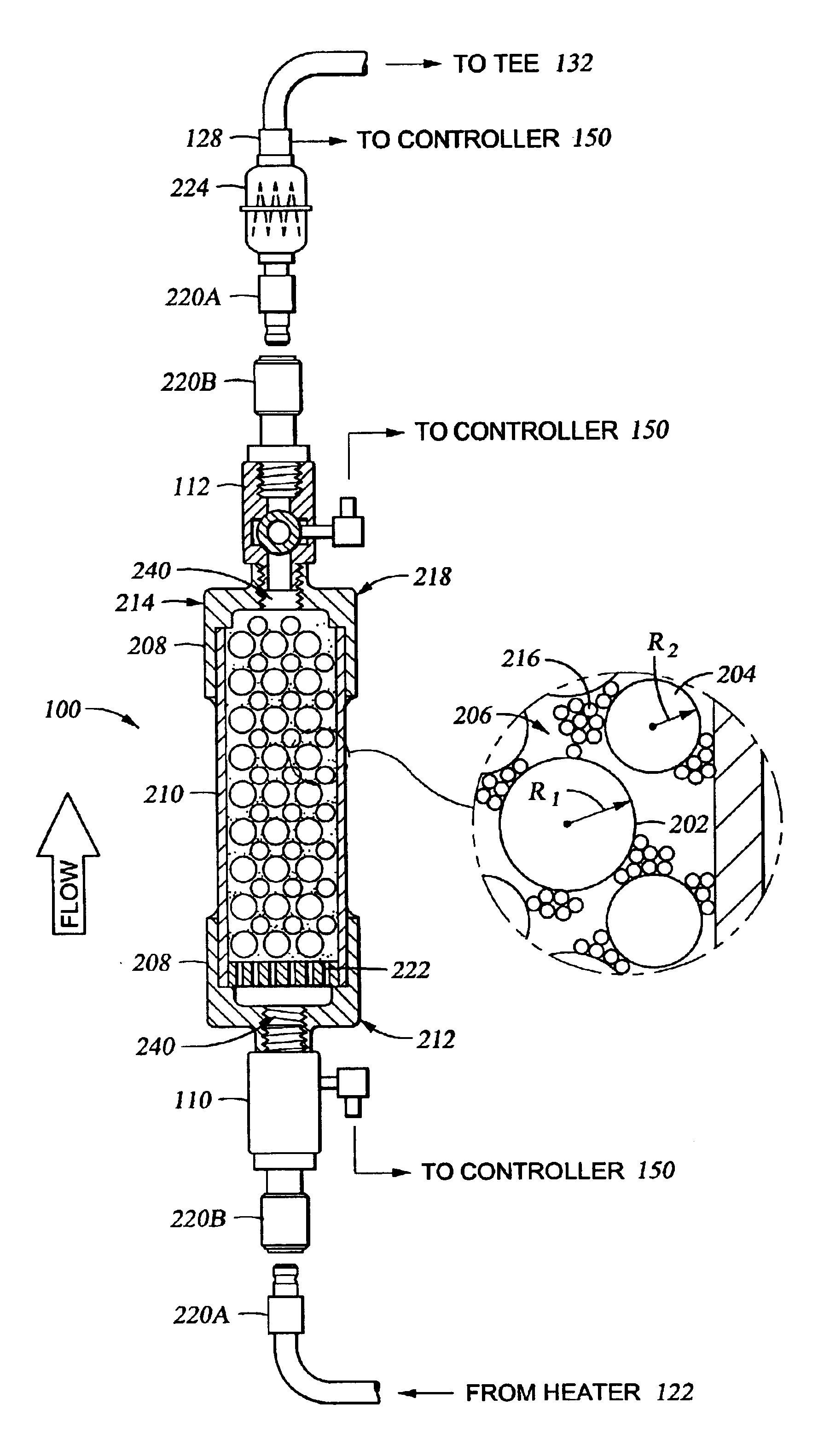
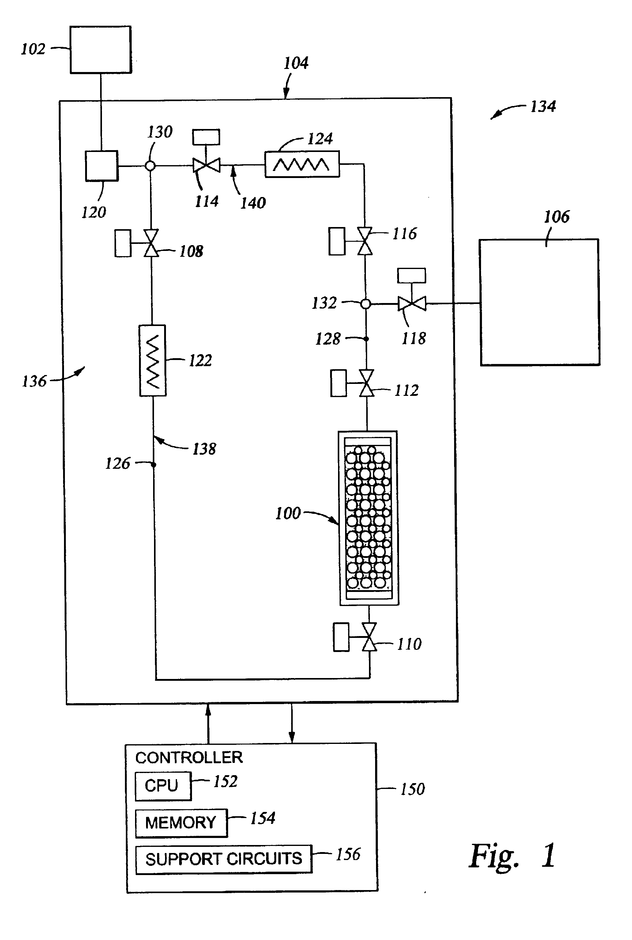
[0021]FIG. 1 generally depicts a simplified schematic of a processing system 134, which in one embodiment, is suitable for micromachining structures on silicon or other materials. The processing system 134 generally includes a processing chamber 106 coupled to a gas panel 104. The processing chamber may be any suitable processing chamber, for example, those available from Applied Materials, Inc. located in Santa Clara, Calif. Exemplary processing chambers include DPS CENTURA® etch chambers, PRODUCER® chemical vapor deposition chambers, DzX® chemical vapor deposition chambers and ENDURA® physical vapor deposition chambers, among others.

[0022]The gas panel 104 generally controls the rate and pressure at which various process and inert gases are delivered to the processing chamber. The number and types of process and other gases delivered to the processing chamber 106 are generally selected based on the process to be performed in the processing chamber 106 coupled thereto. For clarity,...


PUM

PropertyMeasurementUnit
temperatureaaaaaaaaaa
mean diametersaaaaaaaaaa
mean diameteraaaaaaaaaa

Abstract

A method and apparatus for generating gas for a processing system is provided. In one embodiment, an apparatus for generating gas for a processing system includes an unitary, isolatable, transportable canister having a plurality of first spacing elements, a plurality of second spacing elements and a solid material disposed within the canister. The spacing elements have different mean diameters. The solid material is adapted to produce a gas vapor when exposed to a temperature above a predetermined level at a predetermined pressure. In another embodiment, an apparatus for generating gas includes a gas source coupled to a processing chamber by a first gas line. A canister is coupled in-line with the first gas line and contains a solid material that produces a process gas when heated. A heater is disposed between the gas source and the canister to heat gas flowing into the canister.

Description

BACKGROUND OF THE INVENTION[0001]1. Field of the Invention[0002]Embodiments of the invention generally relate to a method and apparatus for subliming a solid to provide a gas to a micromachining processing chamber.[0003]2. Background of the Related Art[0004]Semiconductor processing and micromachining use a wide variety of process gases. As structures and devices become increasingly complex, it would be advantageous to provide greater variety of process chemistries. However, some processes gases may be prohibitively expensive to refine, difficult to handle or suffer from other shortcomings such as highly reliable gas delivery techniques.[0005]Process gases used during semiconductor processing and micromachining are typically provided to the gas panel in liquid or gaseous form from a central source or a supply vessel positioned proximate the gas panel. Some process gases may be generated at or near the gas panel from solid material through a sublimation process. Sublimation is general...

Claims


Application Information

Patent Timeline
Patent Type & Authority Patents(United States)
IPC IPC(8): B01D7/00C23C16/448
CPCC23C16/4481B01D7/00
Inventor GUENTHER, ROLF A.
Owner APPLIED MATERIALS INC
Why Eureka
Try Eureka