Displacement sensor and solenoid valve driver
- Summary
- Abstract
- Description
- Claims
- Application Information
AI Technical Summary
Benefits of technology
Problems solved by technology
Method used
Image
Examples
first embodiment
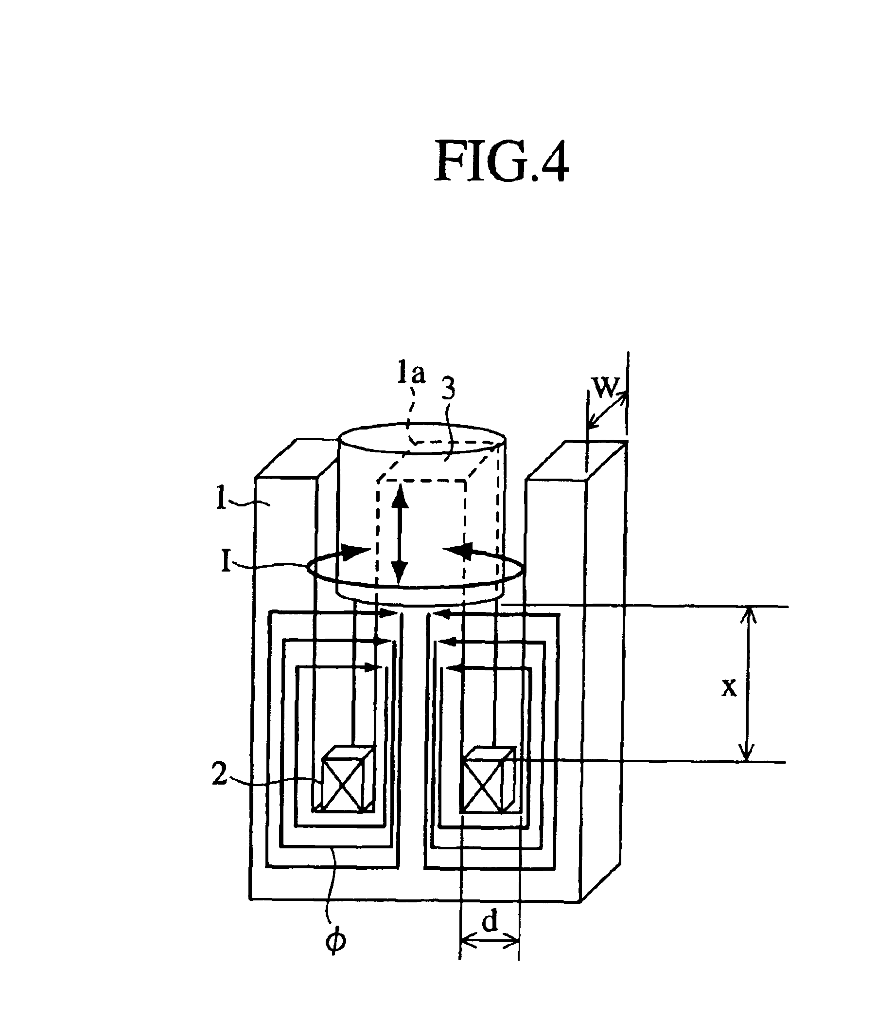
[0050]FIG. 4 is a perspective diagram showing one example of the displacement sensors according to the first embodiment.
[0051]Referring to FIG. 4, reference numeral 1 denotes an E-shaped stator iron core, made of ferromagnetic material, for forming a magnetic path, 2 denotes a coil provided around the base of the central magnet fragment 1a of the E-shaped stator iron core 1, 3 denotes a moving body made of a non-magnetic material movably provided in the top end of the central magnet fragment 1a.
[0052]The operation of the displacement sensor of the first embodiment will next be described.
[0053]When feeding a high-frequency current to the coil 2, an oscillating magnetic field is generated, and an induced current is generated in the moving body 3 depending on the magnetic flux Φ passing through the magnetic path. But no magnetic flux is generated on the top of the E-shaped stator iron core 1, lying above the moving body 3. Because the magnetic field of the magnetic circuit is intercep...
second embodiment
[0058]FIG. 6 is a longitudinal sectional view showing the displacement sensor according to the second embodiment.
[0059]Referring to FIG. 6, reference numeral 11 denotes a shaft moving in an axial direction, 12 denotes a moving element made of ferromagnetic material and secured around the outside of the shaft 11, 13 denotes a stator iron core, having a length substantially equal to that of the moving element 12, for forming a magnetic path, and 14 denotes a coil provided within a concavity 13a formed on the surface of the stator iron core 13 opposing the moving element 12.
[0060]The operation of the displacement sensor of the second embodiment will now be described below.
[0061]When feeding a high-frequency current to the coil 14, the generated magnetic flux Φ flows through the moving element 12 and the stator iron core 13 as shown in FIG. 6. In this state, when, as shown in FIG. 7, the shaft 11 moves upward, the positional relationship between the moving element 12 and the stator iron...
third embodiment
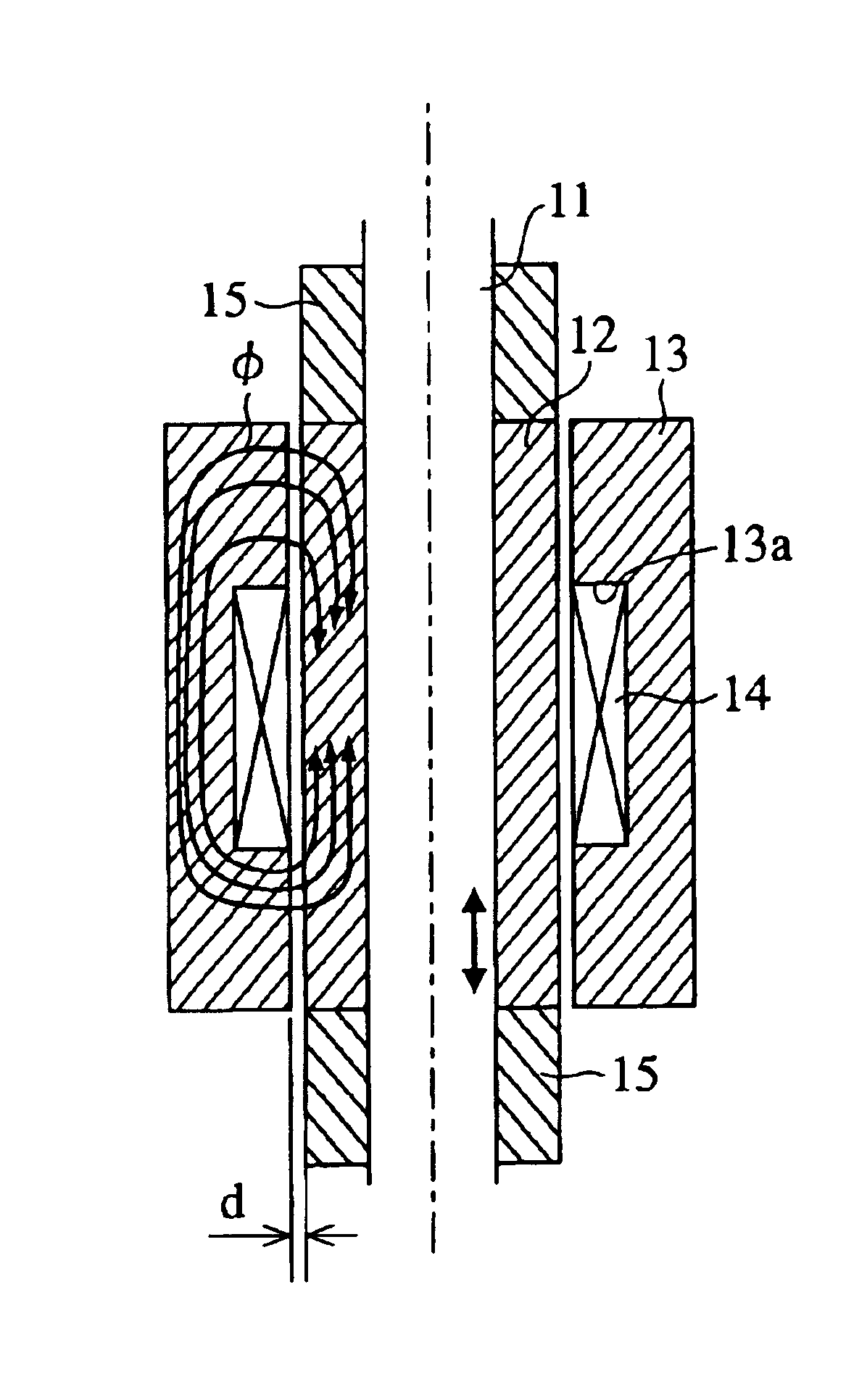
[0063]FIG. 8 is a longitudinal sectional view showing the displacement sensor according to third embodiment.
[0064]Referring to FIG. 8, reference numeral 15 denotes a magnetic-shielding material provided on both end faces of the moving element 12 and made of low-resistance metal. As other components are the same as those of the second embodiment shown in FIGS. 6, 7, the same reference numerals as the second embodiment indicate the same components, and thus descriptions thereof are omitted for brevity's sake.
[0065]The operation of the displacement sensor of the third embodiment will now be described below.
[0066]When feeding a high-frequency current to the coil 14, the generated magnetic flux flows through the moving element 12 and the stator iron core 13 as shown in FIG. 8. In this state, when, as shown in FIG. 9, the shaft 11 moves upward, the positional relationship between the moving element 12 and the stator iron core 13 is changed. At this event, the second embodiment as shown in...
PUM
 Abstract
Description
Claims
Application Information
 - Generate Ideas
- Intellectual Property
- Life Sciences
- Materials
- Tech Scout
- Unparalleled Data Quality
- Higher Quality Content
- 60% Fewer Hallucinations
Browse by: Latest US Patents, China's latest patents, Technical Efficacy Thesaurus, Application Domain, Technology Topic, Popular Technical Reports.
© 2025 PatSnap. All rights reserved.Legal|Privacy policy|Modern Slavery Act Transparency Statement|Sitemap|About US| Contact US: help@patsnap.com


