Eureka AIR delivers breakthrough ideas for toughest innovation challenges, trusted by R&D personnel around the world.

Polishing and cleaning compound device

Inactive Publication Date: 2005-07-12
TSC CORP
View PDF21 Cites 2 Cited by
  • Summary
  • Abstract
  • Description
  • Claims
  • Application Information

AI Technical Summary

Benefits of technology

[0008]Besides, the present invention is that, in a polishing and cleaning compound device in which a polishing device unit for polishing thin disc-shaped work pieces and a cleaning device unit for cleaning the work pieces polished in the polishing device unit are located in series, the cleaning device unit comprises second holding means each of which holds a work piece transported from the polishing device unit in turn, a circle-shaped transport means in which the second holding means are arranged equally on circumference thereof, and a cleaning means which comprises a pair of cleaning tools located so as to grip the work piece and make the pair of the cleaning tools rotate and the work piece rotate in its axis.
[0014]It is preferred that at least one roller for rotation in the polishing device unit makes the work piece move (reciprocate) or revolve elliptically so that a center of the work piece passes through an area in contact with the cylindrical polishing tools. Thus, in the case that the work piece is thin disc-shaped and does not have an opening at a center thereof, it is possible to polish evenly as a whole.
[0018]Furthermore, it is preferred that the polishing process and the cleaning process are overlapped at a specific time to be carried out. Thus, shift from the polishing process to the cleaning process can be carried out smoothly.

Problems solved by technology

In this case, when the work pieces are taken out after polishing, polished surfaces of the work pieces are changed by the slurry clung thereon, so that a disadvantage arises in that the work pieces must be taken out as soon as possible and qualities of the work pieces are changed according to an order in which the work pieces are taken out.
In addition, as disclosed in JP 2001-144057 A, it is preferable that removal of the slurry is carried out every polishing process, but as a result, a disadvantage arises in that the process is complicated.
Furthermore, a disadvantage arises in that abrasive cloth is hardened because of a time interval between the polishing process and the cleaning process, such that a problem of a decrease in a quality of polishing arises.

Method used


Image

  • Polishing and cleaning compound device
  • Polishing and cleaning compound device
  • Polishing and cleaning compound device

Examples


Embodiment Construction

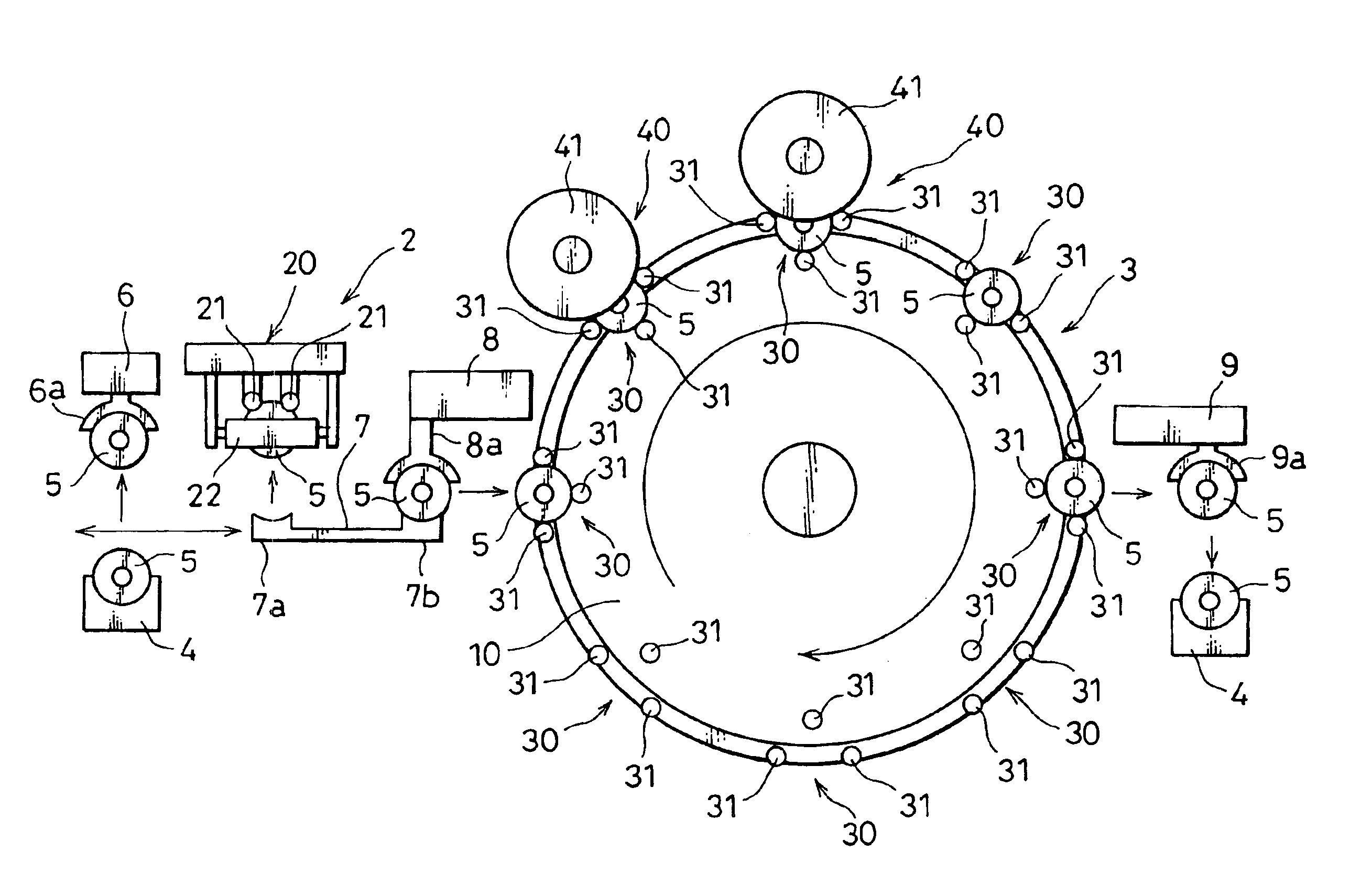
[0032]Hereinafter, the best working modes of the invention are explained according to the drawings.

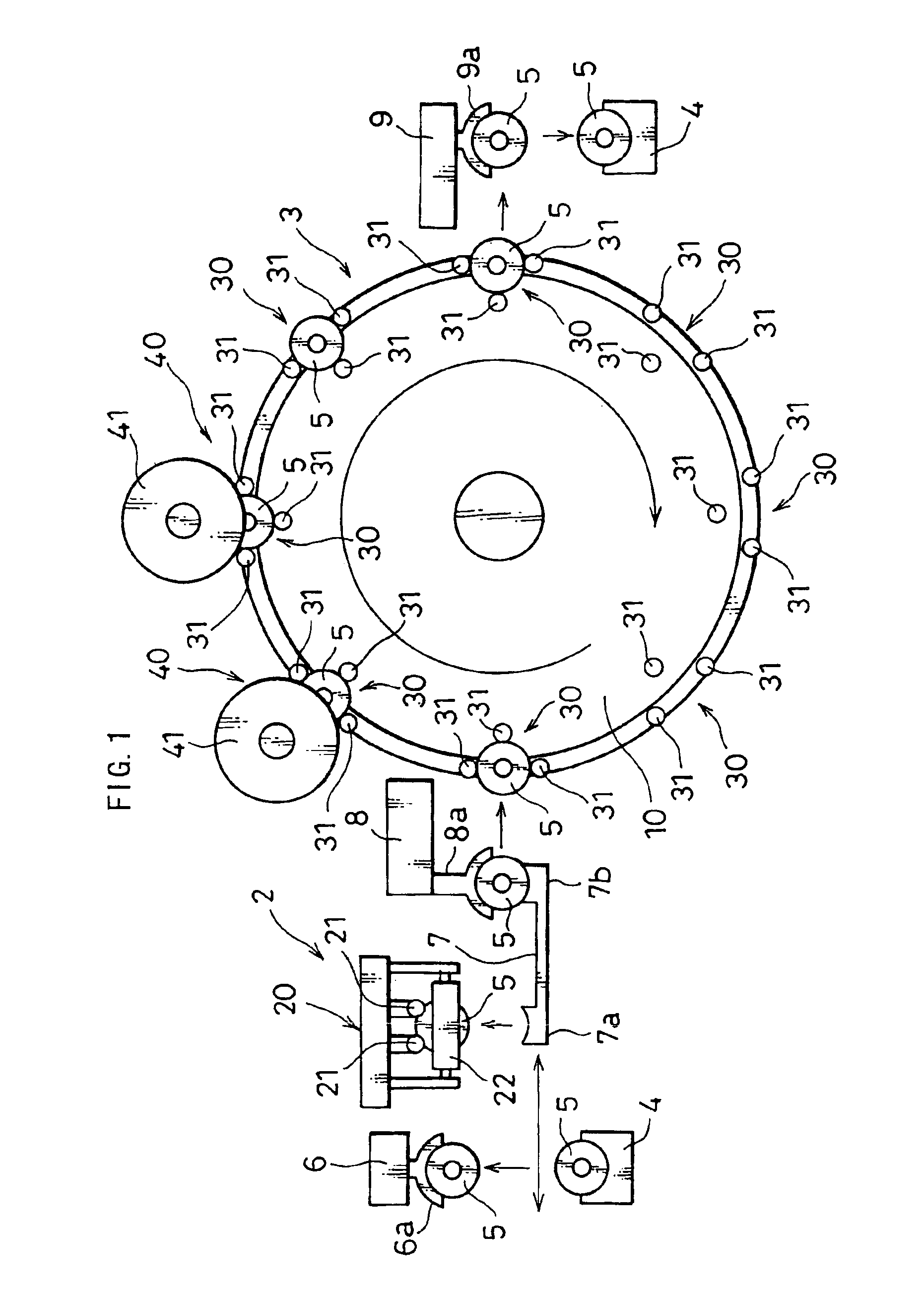
[0033]A polishing and cleaning compound device 1 according to a working mode of the present invention includes at least a polishing device unit 2 and a cleaning device unit 3.

[0034]A thin disc-shaped work piece 5 such as a substrate for a magnetic disc, a semiconductor wafer, a glass substrate for liquid-crystal display, and a glass substrate for a photomask which is installed in a container 4 is gripped by a grip 6a of a lift mechanism 6 and lifted up from the container 4. A career 7 moves to a position where a first holder 7a of the career 7 reaches under the grip 6a, and in this position, the career 7 moves up to receive the work piece 5 on the first holder 7a from the grip 6a.

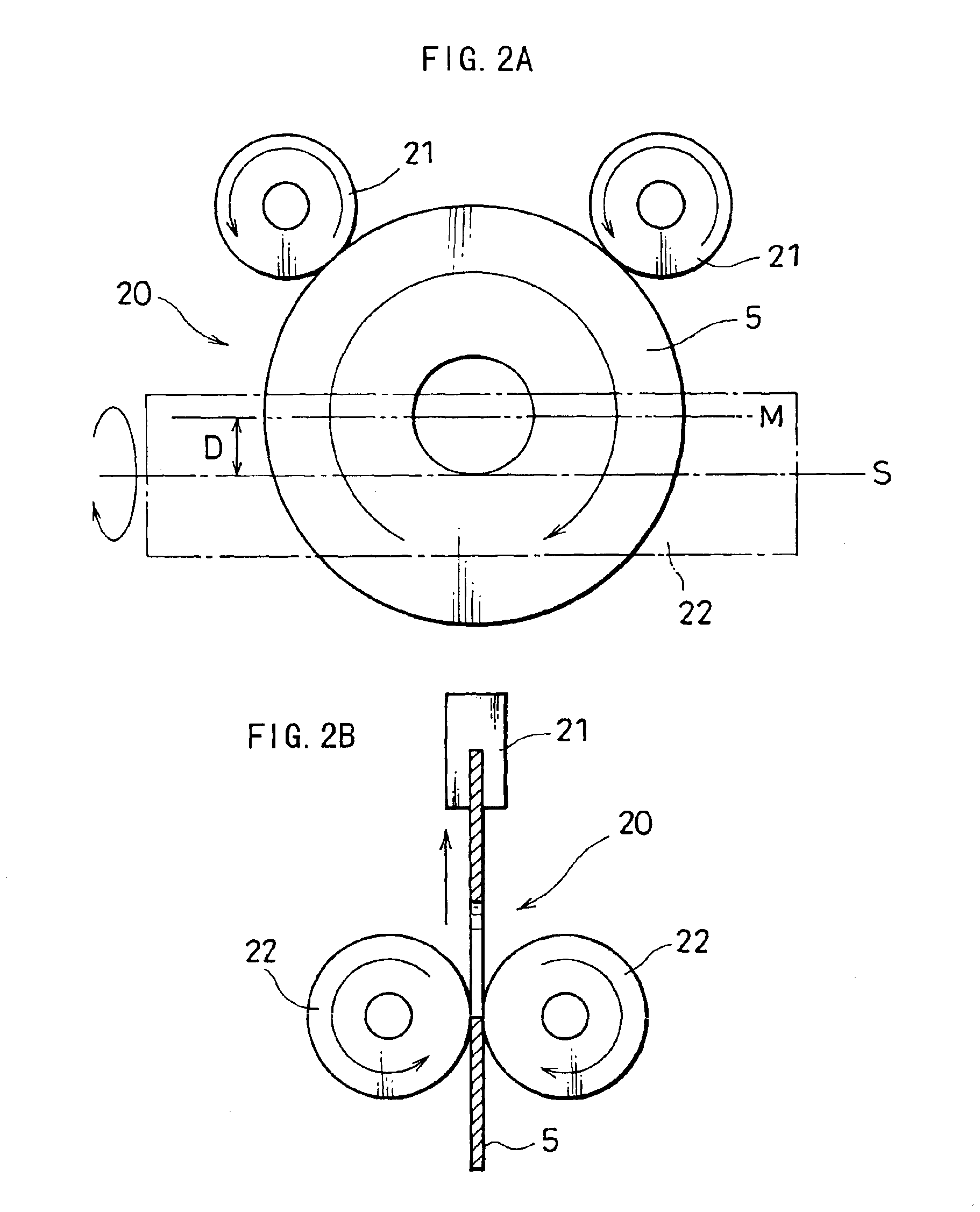
[0035]After the work piece 5 is set on the first holder 7a, the career 7 moves horizontally to a position where the first holder 7a reaches under a polishing mechanism 20, and in the position, the career move...


PUM


Abstract

A polishing and cleaning compound device is provided which polishes and cleans a work piece in series, wherein cleaning is started while the polishing is being terminated. Thus, the polishing and cleaning compound device includes a polishing device unit having a pair of cylindrical polishing tools which vertically grip and hold a work piece transported from a container in which a plurality of thin disc-shaped work pieces are installed, the cylindrical polishing tools being rotated so as to pull the work piece up and polish the work piece as the work piece is rotated by rollers for rotation; and a cleaning device unit which is a circular shaped transporting mechanism and in which a plurality of holding devices hold the work pieces polished in the polishing device unit and move to a specific position in turn to clean the work piece. The polishing process is carried out by supplying abrasive and a cleaning process is carried out by supplying washing water.

Description

BACKGROUND OF THE INVENTION[0001]This invention relates to a polishing and cleaning compound device which polishes and cleans both surfaces of a thin disc-shaped work piece in series such as a substrate for magnetic discs, a wafer, a glass substrate for a liquid-crystal display and a glass substrate for photomask.[0002]JP 2002-254301 A discloses a polishing device which holds careers having a plurality of holes for holding a plurality of work pieces between upper and lower press pratens and makes them revolve and rotate on its own axis in normal and inverse directions alternatively to polish both sides of a plurality of work pieces.[0003]JP 2001-144057 A discloses that, for example, a process for polishing surfaces of wafers is constituted of a plurality of polishing processes such as a rough polishing process, a precise polishing process, and a finish process, whose problem is to well remove slurry which is clung on wafers when the wafers are moved between the polishing stations. A...

Claims


Application Information

Patent Timeline
IPC IPC(8): B24B37/04
CPCB24B37/04
Inventor NAGASHIMA, TOSHIO
Owner TSC CORP
Why Eureka
Eureka Blog
Learn More