Continuous flow microwave heater

a microwave heater and continuous flow technology, applied in microwave heating, electric/magnetic/electromagnetic heating, gas-filled discharge tubes, etc., can solve the problem of relatively complicated arrangemen

Inactive Publication Date: 2005-07-12
KERNFORSCHUNGSZENTRUM KARLSRUHE GMBH
View PDF5 Cites 16 Cited by
  • Summary
  • Abstract
  • Description
  • Claims
  • Application Information

AI Technical Summary

Benefits of technology

[0026]The continuous flow microwave heater is of simple technical design assembled completely from standard components. Microwave shielding structures toward the environment are somehow inherent since the microwave source is a component surrounded by a metal housing. It is provided with cooling ribs and a blower for cooling or with cooling ribs provided with passages connected to a cooling circuit so that a coolant can be conducted through these passages. The applicator is directly connected or it is connected by way of a short hollow conductor piece. By way of the metallic tube stubs, which are connected to the two ends of the dielectric tube, the flow circuit can be completed in a simple manner using two hose connectors.
[0028]It is also an economic advantage that, with an applicator geometry adapted to the load through which the fluid flows, a circulator as protection from waves returning to the microwave source is no longer necessary since the wave emitted by the microwave source is completely dissipated in the load and converted into heat. Such a circulator would be redundant that is it would be installed only as an additional protection device.

Problems solved by technology

Such arrangements are relatively complicated if the microwave component and utilization component are designed as a unit.

Method used


Image

  • Continuous flow microwave heater
  • Continuous flow microwave heater
  • Continuous flow microwave heater

Examples


Embodiment Construction

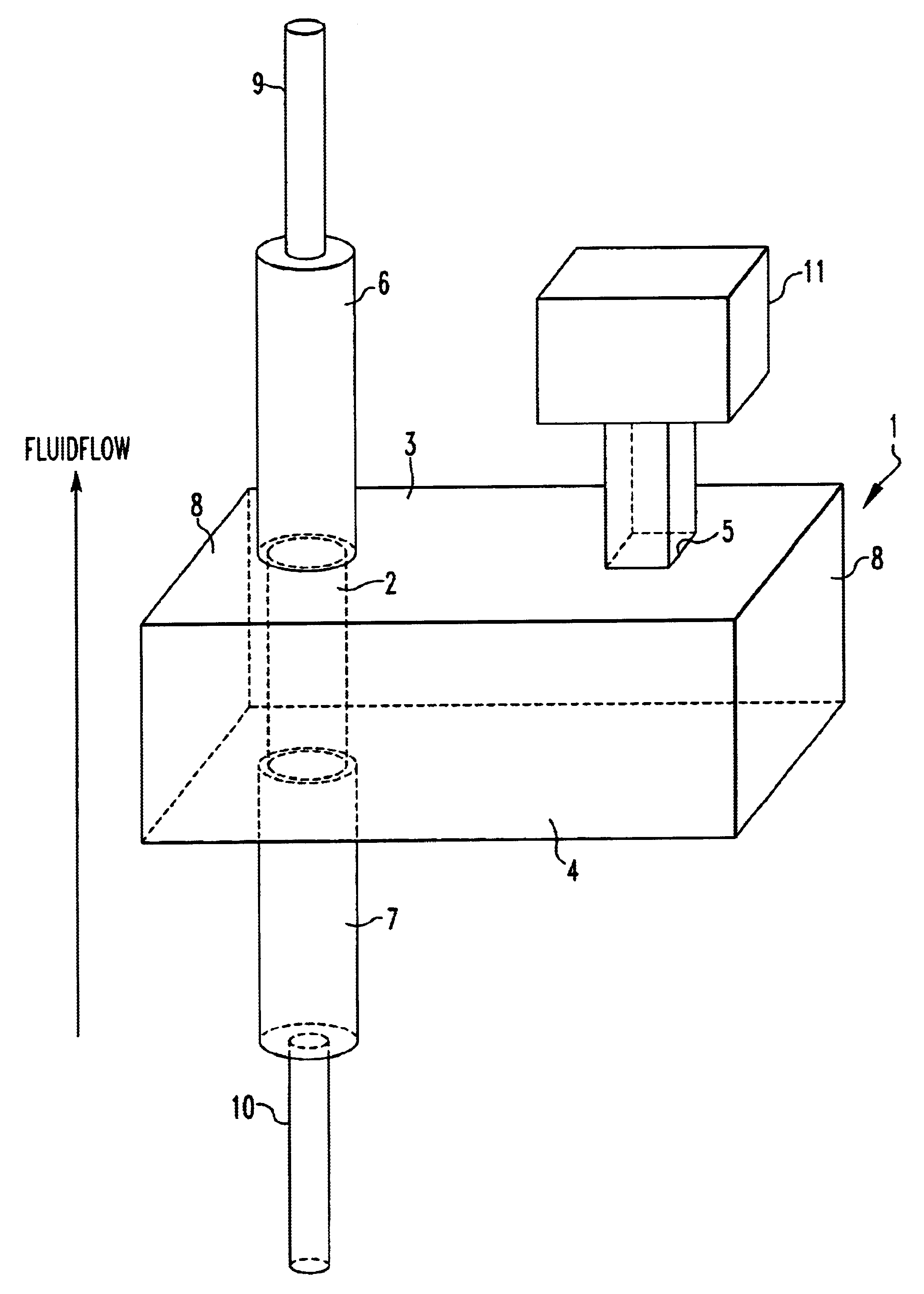
[0034]The continuous flow microwave heater described below operates with a microwave frequency of v=2.45 GHz, which is equivalent to a wavelength of λ≈12 cm in a vacuum. The geometry of the apparatus is based on these values. Two other usable ISM frequencies are for example a lower frequency of 915 MHz and a higher frequency of 5.85 GHz. Usable technical microwave sources operating at these frequencies are commercially available.

[0035]In the embodiment, which will be described below, a magnetron is used as the microwave source. It has for example the following technical data:

[0036]

Microwave Output Energy1000WFrequency2.45GHzVoltage4.2kVCurrent0.33A

[0037]The magnetron is usually manufactured as a unit including the cooling arrangement. At its top, the rectangular hollow conductor is open and provided with a coupling flange. Connected thereto is the applicator 1 at the front end of which, close to the uncoupling opening, an evacuation stub is arranged for an eventually needed evacuati...


PUM


Abstract

In a continuous flow microwave heater for heating a fluid including a microwave source connected to an applicator so as to supply microwave energy to the applicator, the applicator is a rectangular block-like resonator space with opposite front walls and side walls with a microwave in-coupling opening in one of the side walls through which the microwave energy is supplied to the resonator space in which a linearly polarized base mode TE10 is excited. A dielectric tube extends through the resonator space to conduct the fluid to be heated through the applicator, the dielectric tube being so arranged that the microwave energy supplied to the applicator is completely dis-sipated into the fluid flowing through the dielectric tube.

Description

[0001]This is a Continuation-In-Part application of international application PCT / EP02 / 05335 filed May 15, 2002 and claiming the priority of German application 101 28 038.6 filed Jun. 8, 2001.BACKGROUND OF THE INVENTION[0002]The invention relates to a continuous flow microwave heater for heating fluids.[0003]Microwaves are suitable for heating in many ways. They are used in food processing, in households, in the medicine and in industrial materials processing in various ways. Goods being processed may simply be irradiated or a microwave applicator may be part of a microwave power generator for heating such as the well-known household microwave oven or the microwaves may be used for heating or maintaining the temperature of a heat bath in the processing of materials.[0004]The last mentioned is known from DE 199 35 387 A1. In this case, a microwave applicator is arranged at one side wall of a tub such that the side wall is common to the microwave applicator and the tub. The side wall ...

Claims


Application Information

Patent Timeline
Patent Type & Authority Patents(United States)
IPC IPC(8): H05B6/80H05B6/78H05B6/64H05B6/72H05B6/74
CPCH05B6/70H05B6/802
Inventor FEHER, LAMBERTBAUMGARTNER, HARTMUTLINK, GUIDO
Owner KERNFORSCHUNGSZENTRUM KARLSRUHE GMBH
Why Eureka
Try Eureka