Sliding means with built-in moving-magnet linear motor

Active Publication Date: 2005-07-12
NIPPON THOMPSON
View PDF10 Cites 32 Cited by
  • Summary
  • Abstract
  • Description
  • Claims
  • Application Information

AI Technical Summary

Benefits of technology

[0032]The sliding means constructed as stated earlier, as being made as compact as possible in size, realizes space saving in production, storage, conveying, installation and use thereof. Moreover, the sliding means

Problems solved by technology

This system makes the sliding means complicated and bulky in construction.
To this end, there are problems to be solved in conduction system

Method used


Image

  • Sliding means with built-in moving-magnet linear motor
  • Sliding means with built-in moving-magnet linear motor
  • Sliding means with built-in moving-magnet linear motor

Examples


Embodiment Construction

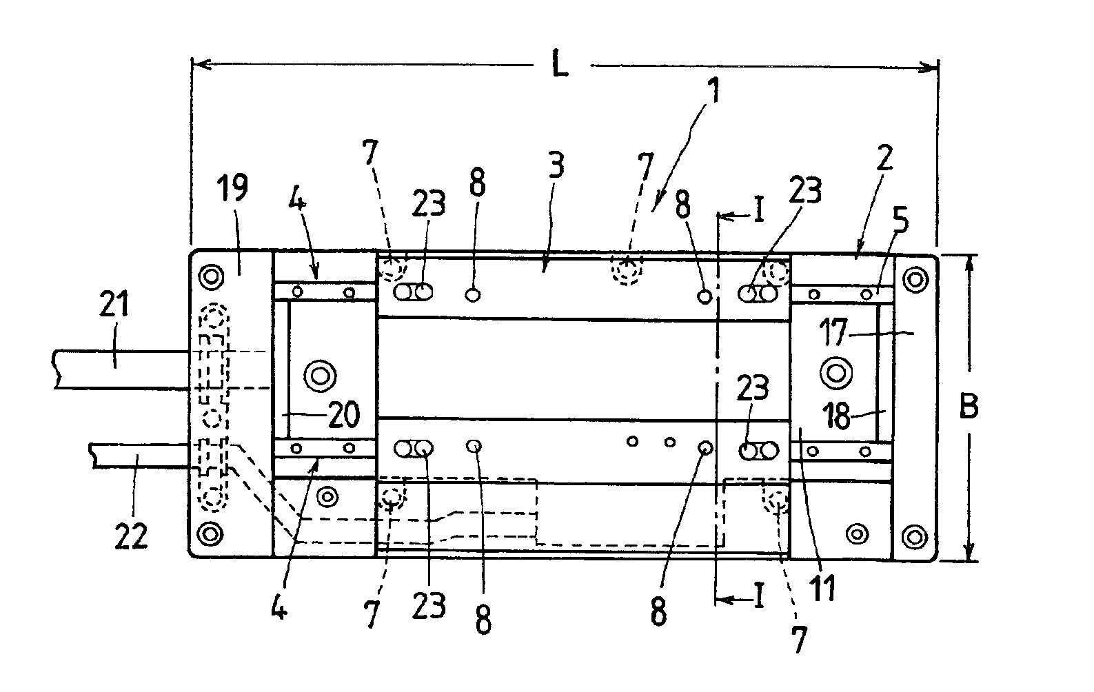
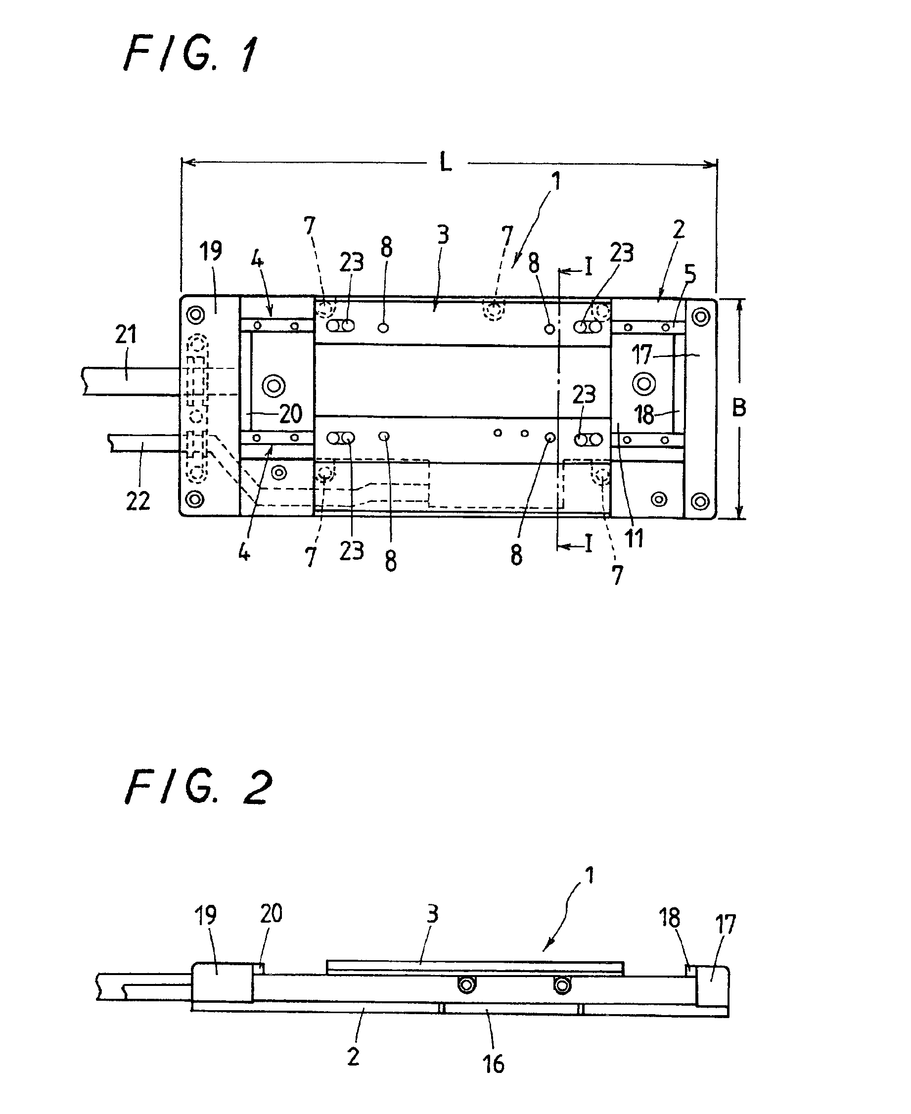
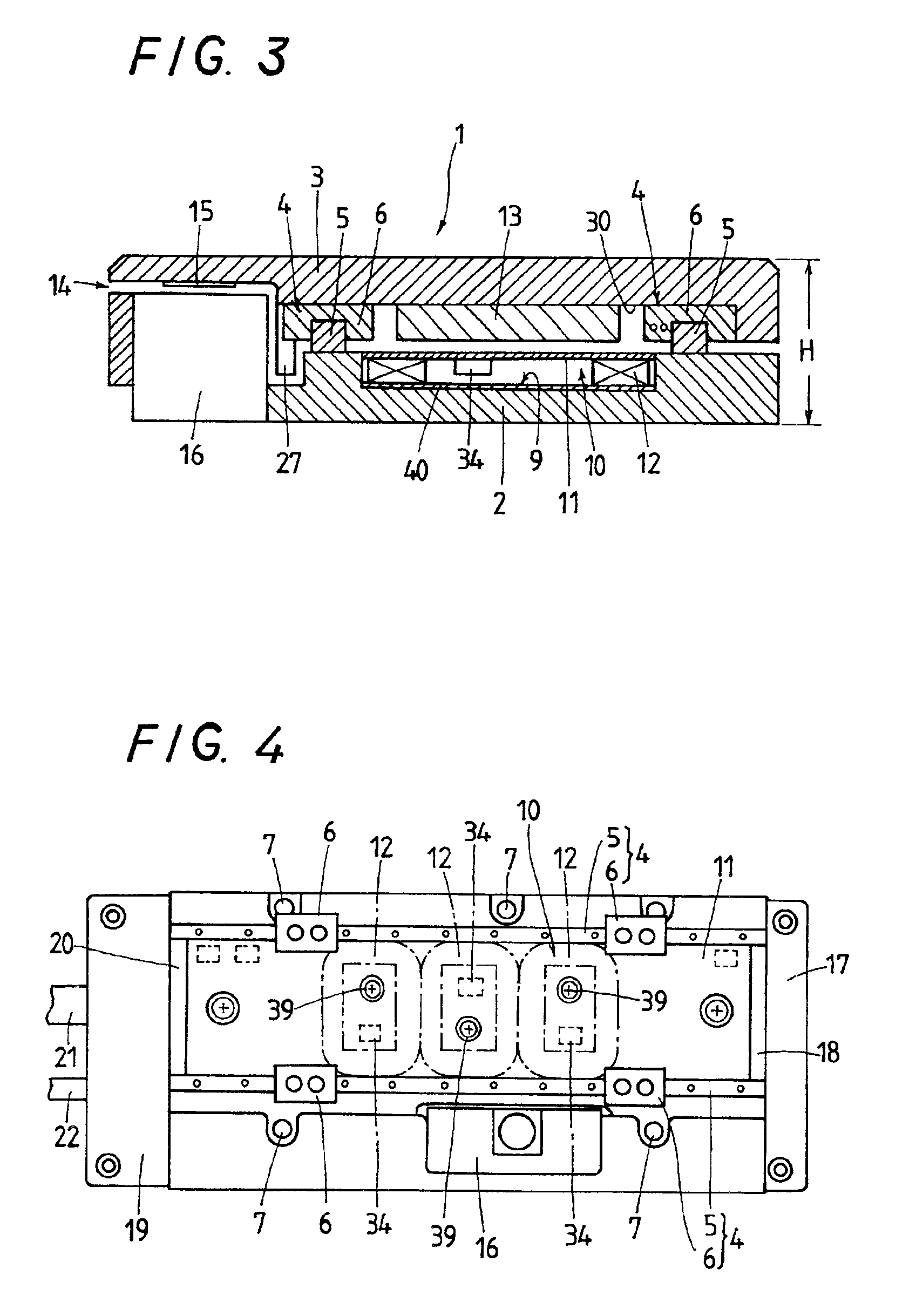
[0048]Preferred embodiments of a sliding means with built-in moving-magnet linear motor according to the present invention will be explained hereinafter in detail with reference to the accompanying drawings.

[0049]Referring to FIGS. 1 to 9, a sliding means 1 is mainly comprised of an elongated steel bed 2 of rectangular shape in top plan view, secured to any stationary machine or instrument, and a steel table 3 of rectangular shape mounted on the bed 2 for linearly sliding movement lengthwise of the bed 2 by virtue of linear motion guide units 4. The linear motion guide units 4 are composed of a pair of track rails 5 secured to the bed 2 with fixing screws so as to extend lengthwise of the bed 2 in parallel with one another, and sliders 6 fitting over and conforming to the track rails 5, two sliders to each rail, for sliding movement relatively of the track rails 5. The table 3, since affixed to the sliders 6 of the linear motion guide units 6, is allowed to move as the sliders 6 run...


PUM


Abstract

A sliding means with built-in moving-magnet linear motor is provided, realizing high-speed operation and much response ability of a table to a stationary bed, and also accurate position control of the table to the bed. With the sliding means of this invention, armature windings carry a three-phase current while a driving circuit is transferred to the external driver to make the bed slim in construction. Thus, the sliding means is reduced in overall height. A field magnet of rare earth permanent magnet is effective in raising flux density, thereby providing high propulsion for the table. An encoder to monitor a position of the table is an optical encoder having an optical linear scale, which contributes to improvement in accurate monitoring. The construction in which the armature windings connected to cords, lines, and so on are placed on the stator side has no fear of causing dust and dirt, thus realizing clean environment.

Description


Claims


Application Information

Patent Timeline
Owner NIPPON THOMPSON
Why Eureka
Try Eureka