
Superconductor output amplifier

a superconductor amplifier and output signal technology, applied in the direction of logic circuits using specific components, pulse generators, pulse techniques, etc., can solve the problems of high noise, low output voltage, and low noise of conventional high-speed superconductor amplifiers used in such circuits

Inactive Publication Date: 2005-07-12
NORTHROP GRUMMAN SYST CORP
View PDF4 Cites 9 Cited by
  • Summary
  • Abstract
  • Description
  • Claims
  • Application Information

AI Technical Summary

Benefits of technology

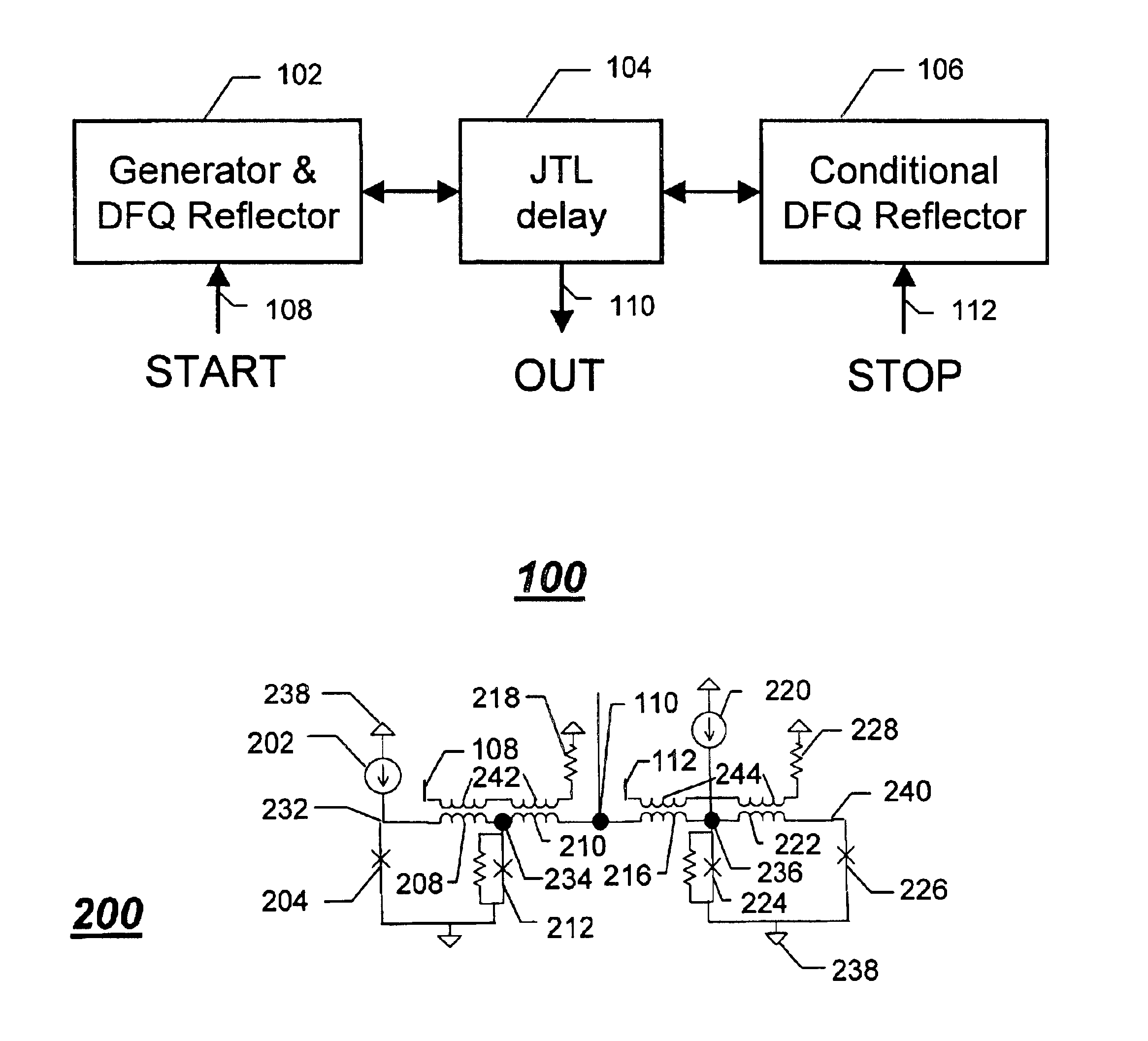
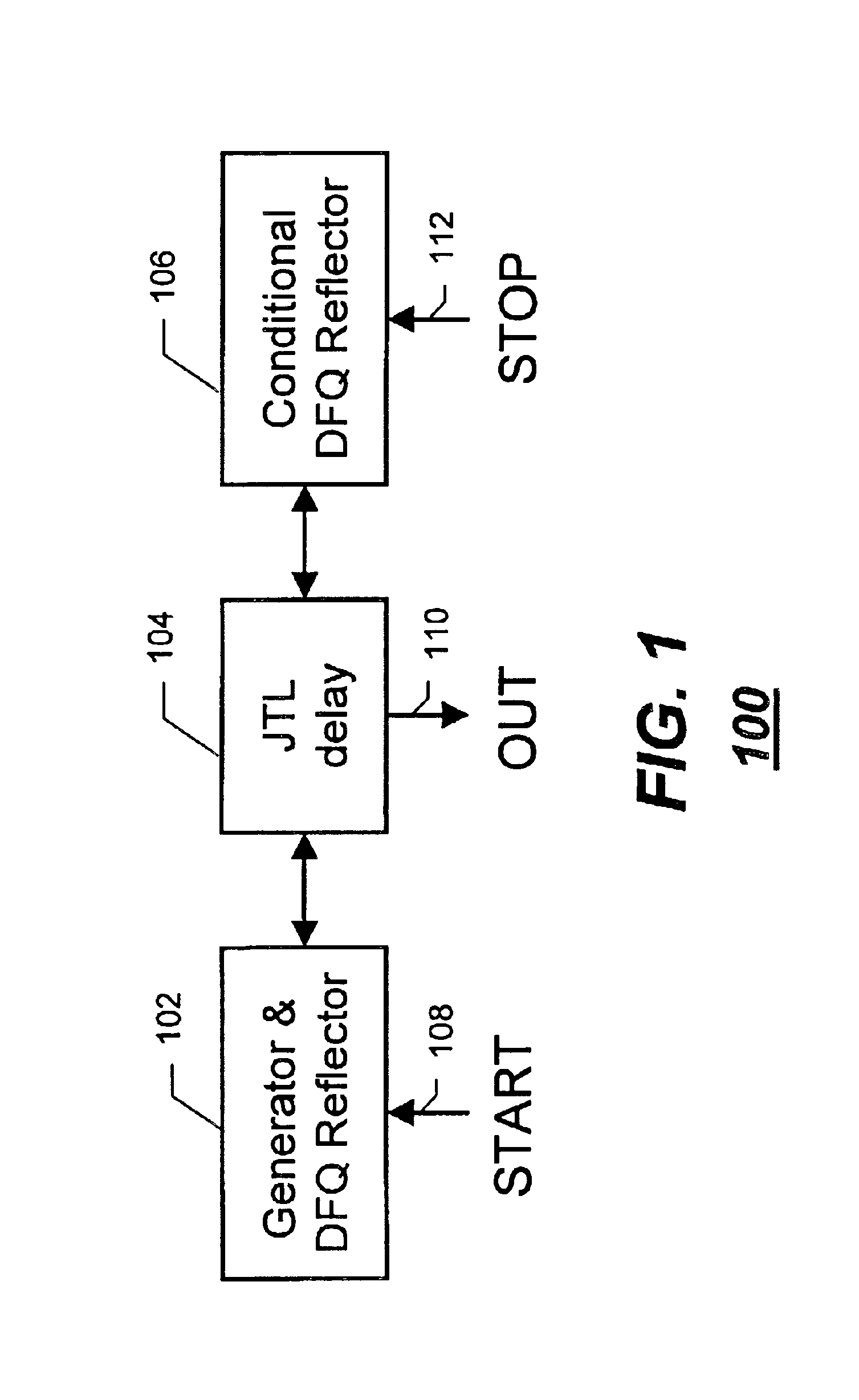
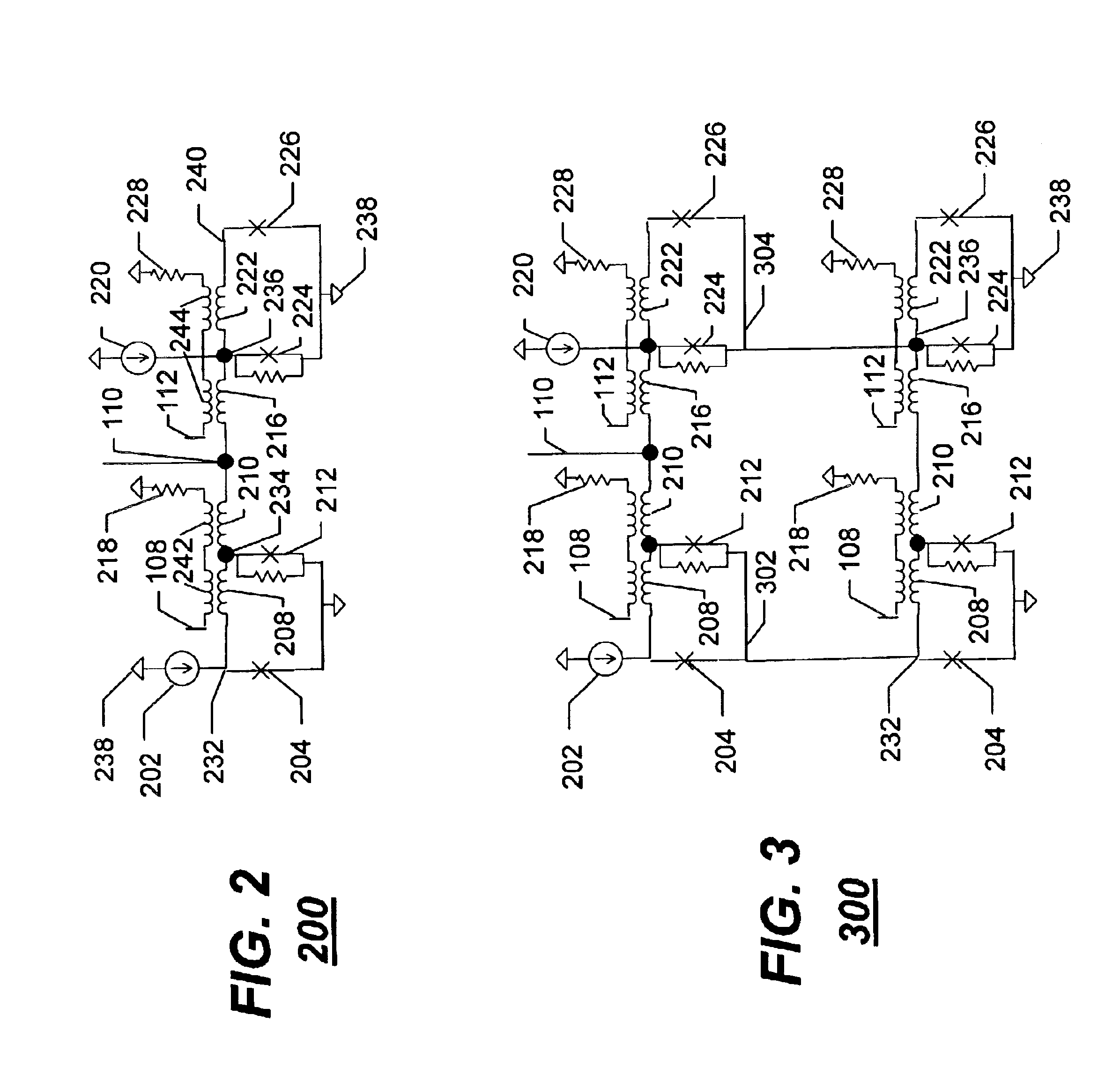
The present invention provides a method for amplifying a superconductor output signal using a single flux quantum (SFQ) pulse. The method involves generating a SFQ pulse by inputting a first signal at a "start" input and reflecting it back and forth between first and second superconductor reflectors. A second signal is then inputted at a "stop" input to interrupt the reflecting of the SFQ pulse and end the generation of the time-disperse plurality of SFQ pulses. An apparatus for amplifying a superconductor output is also provided, including a superconductor delay element and first and second superconductor reflectors for generating a time-disperse plurality of SFQ pulses. An integrated circuit for amplifying a superconductor output is also provided, including a superconductor delay element and first and second superconductor reflectors for generating a time-disperse plurality of SFQ pulses. The technical effects of the invention include improved amplification of superconductor output signals and improved accuracy and reliability of the measurement of magnetic fields.

Problems solved by technology

However, conventional high-speed superconductor amplifiers used in such circuits typically produce extremely low output voltages on the order of, for example, about 0.2 mV.
Such low voltages are difficult to detect and are likely to be associated with a noise-induced high error rate.
As a result, such conventional high-speed superconductor amplifiers may cause a slowdown, or even total corruption, of amplified signals.

Method used


Image

  • Superconductor output amplifier
  • Superconductor output amplifier
  • Superconductor output amplifier

Examples


Embodiment Construction

[0015]In overview form the present disclosure concerns digital superconductor systems. More particularly, various inventive concepts and principles embodied as a method and apparatus for amplifying a superconductor output signal will be discussed and disclosed. The digital superconductor systems and devices of particular interest are those being deployed and developed for operation at high speeds of twenty gigahertz and above, although the concepts and principles have application in other systems and devices.

[0016]The present disclosure is provided to further explain in an enabling fashion the best modes of making and using various embodiments in accordance with the present invention. The disclosure is further offered to enhance an understanding and appreciation for the inventive principles and advantages thereof, rather than to limit the invention in any manner. The invention is defined solely by the appended claims including any amendments made during the pendency of this applicat...


PUM


Abstract

A single flux quantum (SFQ) pulse is generated (502) by injecting a superconductor output signal as a first signal at a “start” input (108) coupled to a superconductor delay element (104). The SFQ pulse is reflected (504) back and forth between first and second superconductor reflectors (102, 106) coupled to opposite ends of the superconductor delay element, thereby generating a time-disperse plurality of SFQ pulses at an output (110) coupled to the superconductor delay element. Thereafter, a second signal is input at a “stop” input (112) coupled to one of the first and second superconductor reflectors, thereby interrupting (506) the reflecting of the SFQ pulse at the one of the first and second superconductor reflectors, thus ending the generating of the time-disperse plurality of SFQ pulses at the output.

Description

RELATED APPLICATIONS[0001]This application is related to co-pending application Ser. No. 10 / 410,923, filed concurrently herewith and entitled “Superconductor Ballistic RAM,” the contents of which are incorporated herein by reference.FIELD OF THE INVENTION[0002]This invention relates in general to digital superconductor circuits, and more specifically to a method and apparatus for amplifying a superconductor output signal.BACKGROUND OF THE INVENTION[0003]Digital superconductor circuits, operating at cryogenic temperatures and at low voltage levels, need to communicate to the outside world at high speed on the order of, for example, 20 GHz. However, conventional high-speed superconductor amplifiers used in such circuits typically produce extremely low output voltages on the order of, for example, about 0.2 mV. Such low voltages are difficult to detect and are likely to be associated with a noise-induced high error rate. As a result, such conventional high-speed superconductor amplifie...

Claims


Application Information

Patent Timeline
Patent Type & Authority Patents(United States)
IPC IPC(8): H03F19/00H03K3/38H03K3/00H03K5/02
CPCH03F19/00H03K3/38H03K5/02
Inventor HERR, QUENTIN P.
Owner NORTHROP GRUMMAN SYST CORP
Learn More