Transflective liquid crystal display with particular first and second adjusted thickness and method of fabricating the same

a liquid crystal display and transceiver technology, applied in non-linear optics, instruments, optics, etc., can solve the problems of increased power consumption of backlight, and poor visibility of display

Inactive Publication Date: 2005-07-12
LG DISPLAY CO LTD
View PDF3 Cites 80 Cited by
  • Summary
  • Abstract
  • Description
  • Claims
  • Application Information

AI Technical Summary

Benefits of technology

[0034]Accordingly, the present invention is directed to a transflective liquid crystal display and a method of fabricatin

Problems solved by technology

However, the backlight of the transmission type LCD consumes 50% or more of the total power consumed by the LCD device.
Providing a backlight therefore increases power consumption.
The reflection type LCD using the reflection of ambient light is disadvantageous in that a visibility of the display is extr

Method used


Image

  • Transflective liquid crystal display with particular first and second adjusted thickness and method of fabricating the same
  • Transflective liquid crystal display with particular first and second adjusted thickness and method of fabricating the same
  • Transflective liquid crystal display with particular first and second adjusted thickness and method of fabricating the same

Examples


first embodiment

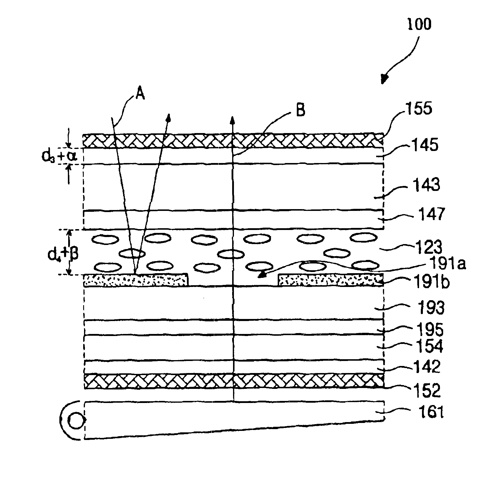
[0065]FIG. 6, a schematic cross-sectional view of a transflective LCD device 100 illustrating an operation of such devices according to the present invention. For convenience, the color filters (the reference numeral 17 of FIG. 1) are not shown in FIG. 6 because they do not affect the polarization state of light. Also, some of explanation will be omitted if not necessary.

[0066]As shown in FIG. 6, the transflective LCD device 100 includes upper and lower substrates 143 and 154 and an interposed liquid crystal layer 123 that has an optical retardation of λ / 4. A common electrode 147 is formed on the upper substrate 143. On the other surface of the upper substrate 143, an upper quarter wave plate (QWP) 145 (often referred to as an upper retardation film), which has a phase difference λ / 4, and an upper polarizer 155 are successively formed thereon.

[0067]A transparent electrode 195 is formed on the lower substrate 154. A passivation layer 193 and a reflective electrode 191b are successive...

second embodiment

[0081]FIG. 9 is a schematic cross-sectional view of a transflective LCD device according to the For convenience, the color filters (the reference numeral 17 of FIG. 1) are not shown in FIG. 9 because they do not affect the polarization state of light.

[0082]As shown in FIG. 9, the transflective LCD device 200 includes upper and lower substrates 217 and 229 and an interposed liquid crystal layer 221. The upper substrate 217 includes a common electrode 219 on the surface facing into the lower substrate 229. On the other surface of the upper substrate 217, an upper quarter wave plate (QWP) 215, an upper half wave plate (HWP) 213, and an upper polarizer 211 are successively formed thereon. The upper HWP 213 has an optical retardation of 270 nm (λ / 2; at λ=550 nm) and the upper QWP 215 has an optical retardation of 140 nm (λ / 4; at λ=550 nm). The upper HWP 213 and the upper QWP 215 act as first and second upper retardation films, respectively.

[0083]Still referring to FIG. 9, the lower subs...


PUM


Abstract

The invention relates to a transflective liquid crystal display device that has a high contrast ratio. The transflective liquid crystal panel includes a homogeneous liquid crystal such that the transflective liquid crystal display device will have an optical retardation when the voltage is applied. Therefore, in order to compensate the optical retardation caused by this liquid crystal, a thickness of the liquid crystal layer is adjusted. Moreover, a thickness of the retardation film is also adjusted. Accordingly, the complete dark state and the high contrast ratio are achieved in the liquid crystal display.

Description

[0001]This is a divisional application of application Ser. No. 09 / 850,186 filed on May 8, 2001 now U.S. Pat. No. 6,657,689. The present invention claims the befit of Korean Patent Application No. P2000-24481 filed in Korea on May 8, 2000, which is hereby incorporated by reference.BACKGROUND OF THE INVENTION[0002]1. Field of the Invention[0003]The present invention relates to a liquid crystal display, and more particularly, to a transflective liquid crystal display and method of fabricating the same. Although the present invention is suitable for a wide scope of applications, it is particularly suitable for a high contrast ratio.[0004]2. Discussion of the Related Art[0005]In general, a liquid crystal display (LCD) is classified as a transmission type and a reflection type depending on implementing an internal or external light source. The transmission type has a liquid crystal display panel, which does not emit light itself, and has a backlight as a light-illuminating section.[0006]T...

Claims


Application Information

Patent Timeline
IPC IPC(8): G02F1/13G02F1/1333G02F1/139G02F1/13363
CPCG02F1/133371G02F1/13363G02F1/1393G02F2001/133638G02F2202/40G02F2203/09G02F2413/04G02F2413/08G02F1/133638G02F1/136
Inventor BAEK, HEUM-LL
Owner LG DISPLAY CO LTD
Why Eureka
Try Eureka