Dot gain calibration method and apparatus

a technology of gain and calibration method, applied in the field of dot gain calibration method and apparatus, can solve the problems of high cost of current calibration cycle on-press compensation, difficult and time-consuming task, and high cost of above-cycl

Inactive Publication Date: 2005-07-12
KODAK IL
View PDF16 Cites 8 Cited by
  • Summary
  • Abstract
  • Description
  • Claims
  • Application Information

AI Technical Summary

Benefits of technology

[0047]Preferably, said basic shapes are preselected such that superposition of selected basic shapes from different ones of said plurality of patches allows simulation of any one of a range of screen parameters sets.

Problems solved by technology

The above cycle is very expensive and time consuming and the curve is only valid as long as conditions remain exactly the same.
Another common technique used in press sites due to the high cost of the current calibration cycle is on-press compensation.
This is a difficult and time consuming task, that becomes even more difficult and almost impossible as use of high screen ruling and FM screening gains popularity.
Even when a dot gain measurement cycle has been performed for a given paper and screen set, the validity of the tone reproduction curve is limited to a time frame, as paper and press characteristics often change over time.
Furthermore, conventional calibration methods are manual, and therefore prone to operator mistakes.
There is no closed-loop process of feed back from press to CTP (Computer to Plate) or CTF (Computer to Film) devices and therefore the accurate reproduction of color cannot be fully automated.
Currently, it is difficult to make sure that the different locations accurately print the same color.
There is only a limited number of sites in the world which have the capability to make such cylinders.
A further kind of printing that is not suited to the above process is printing using direct imaging presses.
Direct imaging presses use direct-imaging waterless printing plates with sets of ink for which the existing dot-gain calibrations are unsuited.
However, with current trends this becomes more difficult.

Method used


Image

  • Dot gain calibration method and apparatus
  • Dot gain calibration method and apparatus
  • Dot gain calibration method and apparatus

Examples


Embodiment Construction

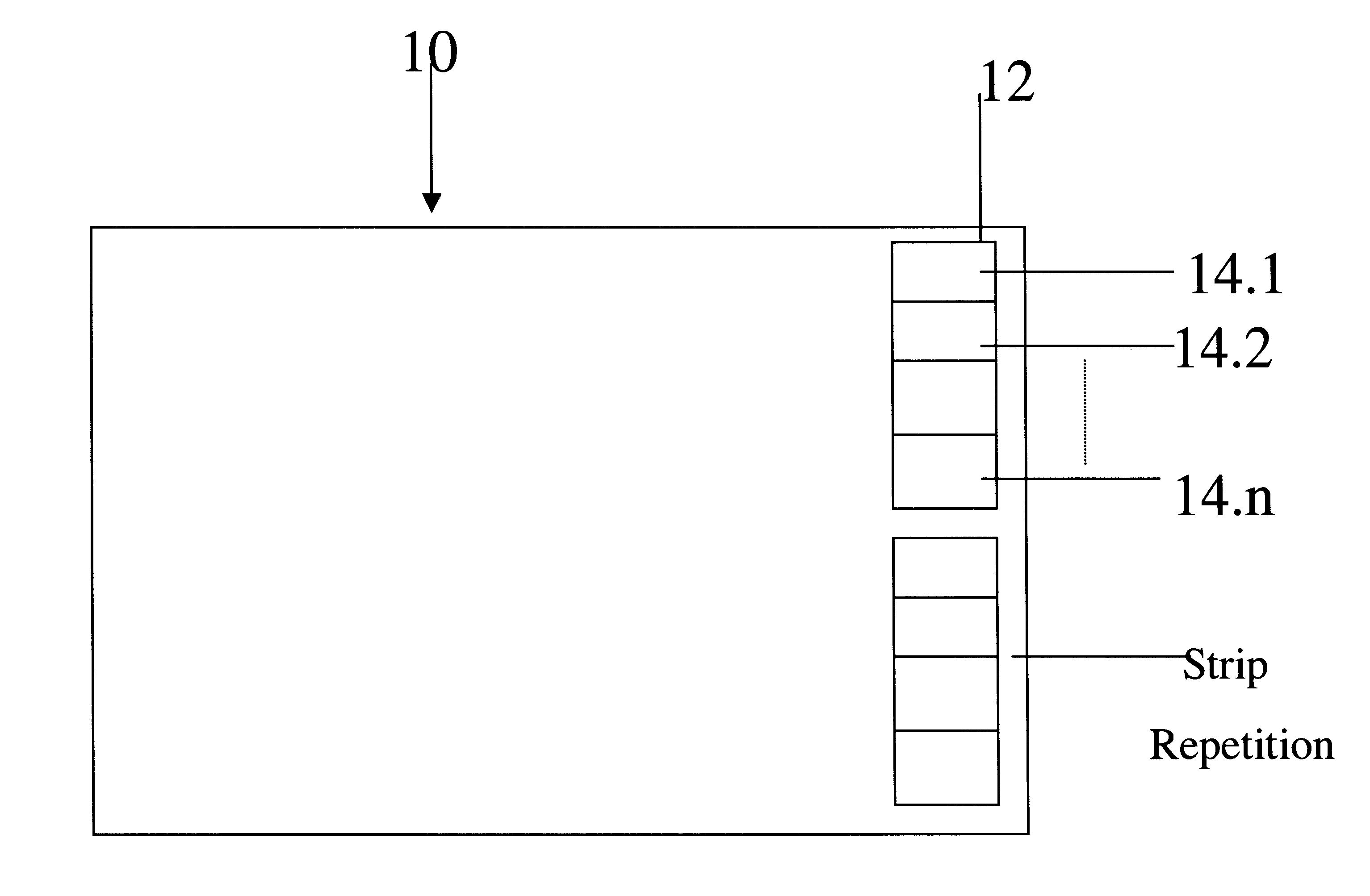
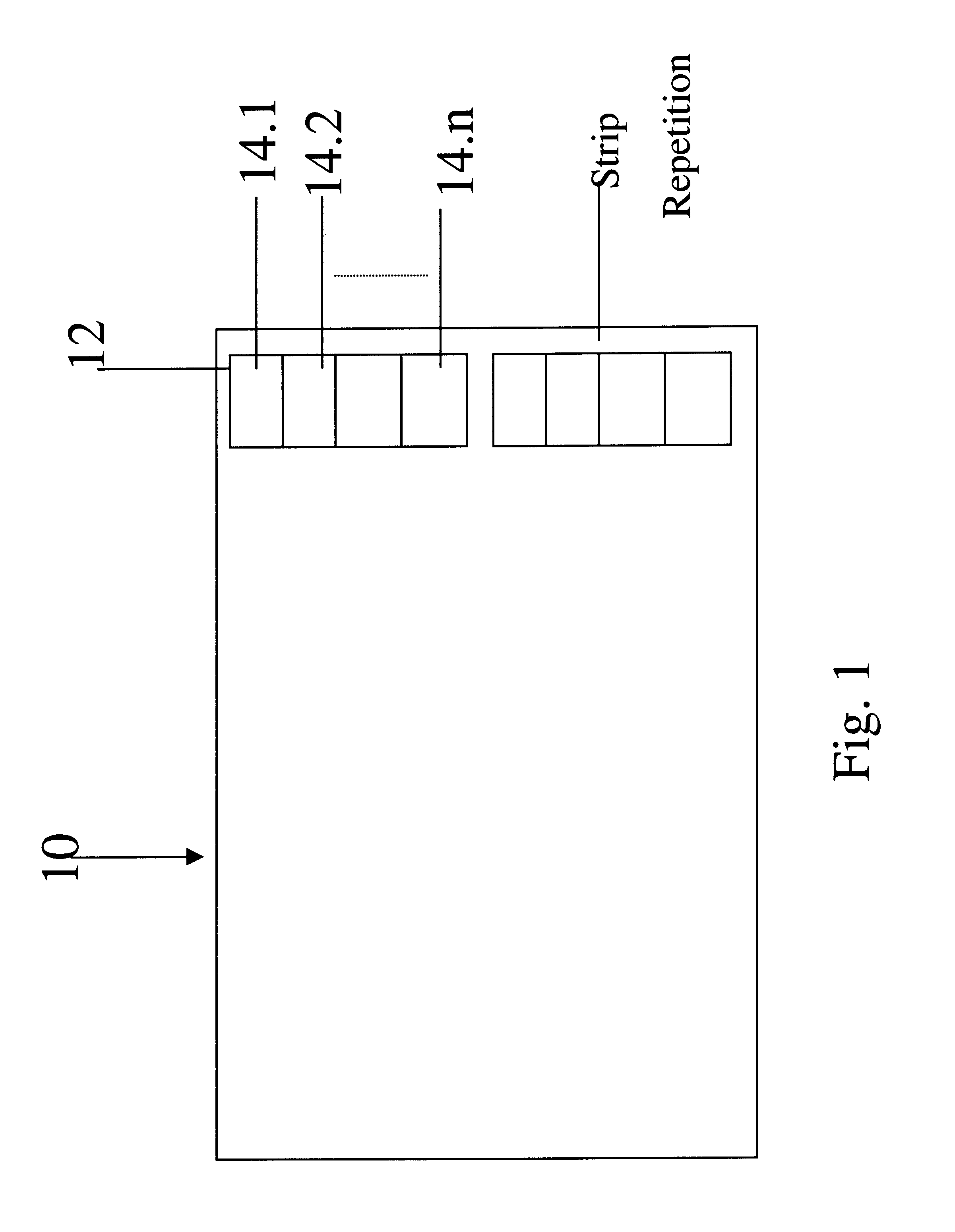
[0104]The present embodiments disclose a system for dot gain calibration which is easy to carry out and therefore suitable for closed loop implementation, including scenarios in which parts of the print process are carried out remotely from each other. The system involves the incorporation onto the printing plate of a calibration strip. The content of the strip is standard, so that color measurements carried out on paper printed from the calibration strip indicate the dot gain under the current print conditions.

[0105]The principles and operation of a dot gain calibration method and apparatus according to the present invention may be better understood with reference to the drawings and accompanying descriptions.

[0106]Before explaining at least one embodiment of the invention in detail, it is to be understood that the invention is not limited in its application to the details of construction and the arrangement of the components set forth in the following description or illustrated in...


PUM


Abstract

A method for providing in use estimation of dot gain in digital printing using digital printing plates, the method comprising: applying to a digital printing plate a calibration strip, the strip comprising at least one set of patches, each patch comprising a plurality of dots at a predetermined gray level within said dynamic range, gray levels of said set of patches being distributed over said dynamic range, printing from said calibration strip under a current set of printing conditions, measuring intensities of said printing, and interpolating from said measurements to generate a curve of dot gain over said dynamic range. The curve can then be used to compensate. When moving to a different set of printing conditions, a single test print is then carried out and a new dot gain estimation is available.

Description

RELATIONSHIP TO EXISTING APPLICATIONS[0001]The present application claims priority from U.S. Provisional Patent Application No. 60 / 382,525 filed May 22, 2002.FIELD AND BACKGROUND OF THE INVENTION[0002]The present invention relates to a dot gain calibration method and apparatus and, more particularly, but not exclusively to dot gain calibration for use with a pre-press system, press or proofing printer.[0003]Dot gain on a printed sheet is an increase in halftone dot size in comparison with dot size on the printing plate. The magnitude of the dot gain depends on factors such as the ink absorption characteristics of the paper, the ink, the screening parameters and the press variables.[0004]The total measured dot gain on the paper is a combination of two separate and unrelated gain factors; plate-related dot gain and press-related dot gain factors. The two gains may be dealt with in any calibrating process to compensate for the dot gain, and may be considered either separately or jointl...

Claims


Application Information

Patent Timeline
Patent Type & Authority Patents(United States)
IPC IPC(8): B41C1/10B41B1/00H04N1/60H04N1/407
CPCB41B1/00B41C1/1075H04N1/4078H04N1/6033
Inventor KOIFMAN, IGALWEISS, ALEXFISHER, YARON
Owner KODAK IL
Why Eureka
Try Eureka