Diffraction grating element

a grating element and diffraction technology, applied in the direction of optical radiation measurement, instruments, spectrometry/spectrophotometry/monochromators, etc., can solve the problems of communication errors, large loss of signal light, and waveform deterioration of signal light, so as to achieve high workability when forming diffraction grating, reduce temperature dependence of light emission position, and constant diffraction efficiency

Active Publication Date: 2005-07-12
SUMITOMO ELECTRIC IND LTD
View PDF5 Cites 13 Cited by
  • Summary
  • Abstract
  • Description
  • Claims
  • Application Information

AI Technical Summary

Benefits of technology

[0008]The present invention has been accomplished in order to solve the above problem, and an object of the present invention is to provide a diffraction grating element that allows the temperature control mechanism to be dispensed with or simplified.
[0017]In the case where an impurity is added to the transparent plate, the impurity is preferably any element among Ge, P, and B. Alternatively, the impurity is also preferably element Ti. For example, by adding an impurity of an appropriate concentration by means of VAD or CVD, or the like, the rate of change in the period per unit length with respect to a temperature change of the diffraction grating formed to the transparent plate, that is, the linear expansion coefficient of the diffraction grating can be afforded the desired value. The section of the transparent plate where the diffraction grating is formed preferably is made of silica glass, and, in this case, the workability when forming the diffraction grating is highly superior.
[0018]In the case of the diffraction grating element according to the present invention, the distribution of material in the thickness direction of the transparent plate, that is, the linear expansion coefficient distribution, is preferably symmetrical. In this case, the occurrence of warp of the transparent plate is suppressed even in the event of a temperature change. In addition, the diffraction grating is preferably formed in the center in the thickness direction of the transparent plate. Here, the temperature dependence of the light emission position is also reduced.
[0019]In the case of the diffraction grating element according to the present invention, the diffraction efficiency is preferably substantially polarization-independent. As a result, even when the polarization state of the incident light is not constant, the incident light can be diffracted with constant diffraction efficiency without using other optical elements as required conventionally (polarization separation element, polarization composing element, and so forth).

Problems solved by technology

In a case where the diffraction grating element is used in a WDM optical communication system, when the diffraction angle of the diffraction grating element changes, the loss of signal light is therefore large or the waveform of the signal light deteriorates, and hence a communication error sometimes occurs.
However, the provision of the temperature control mechanism provokes an increase in the system costs and a system cost increase is also provoked due to the need for a supply of electrical power to the temperature control mechanism.

Method used


Image

  • Diffraction grating element
  • Diffraction grating element
  • Diffraction grating element

Examples


Embodiment Construction

[0034]Referring to the attached drawings, embodiments of the present invention will be described in detail below with. The same reference symbols have been assigned to the same elements or parts in the description of the drawings, and hence repetitive description is omitted here. Further, a xyz Cartesian coordinate system is sometimes shown in the drawings in order to facilitate the description.

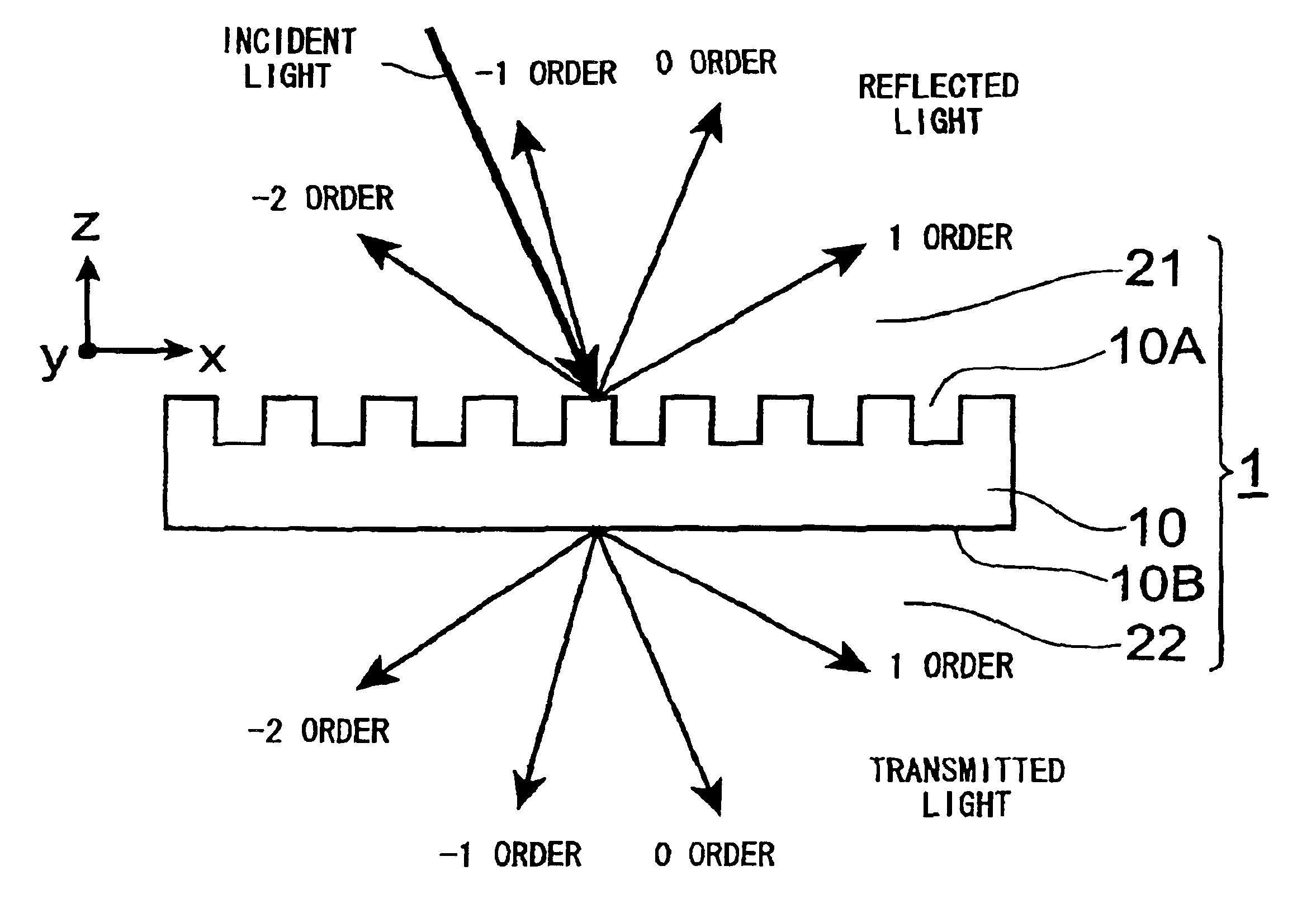
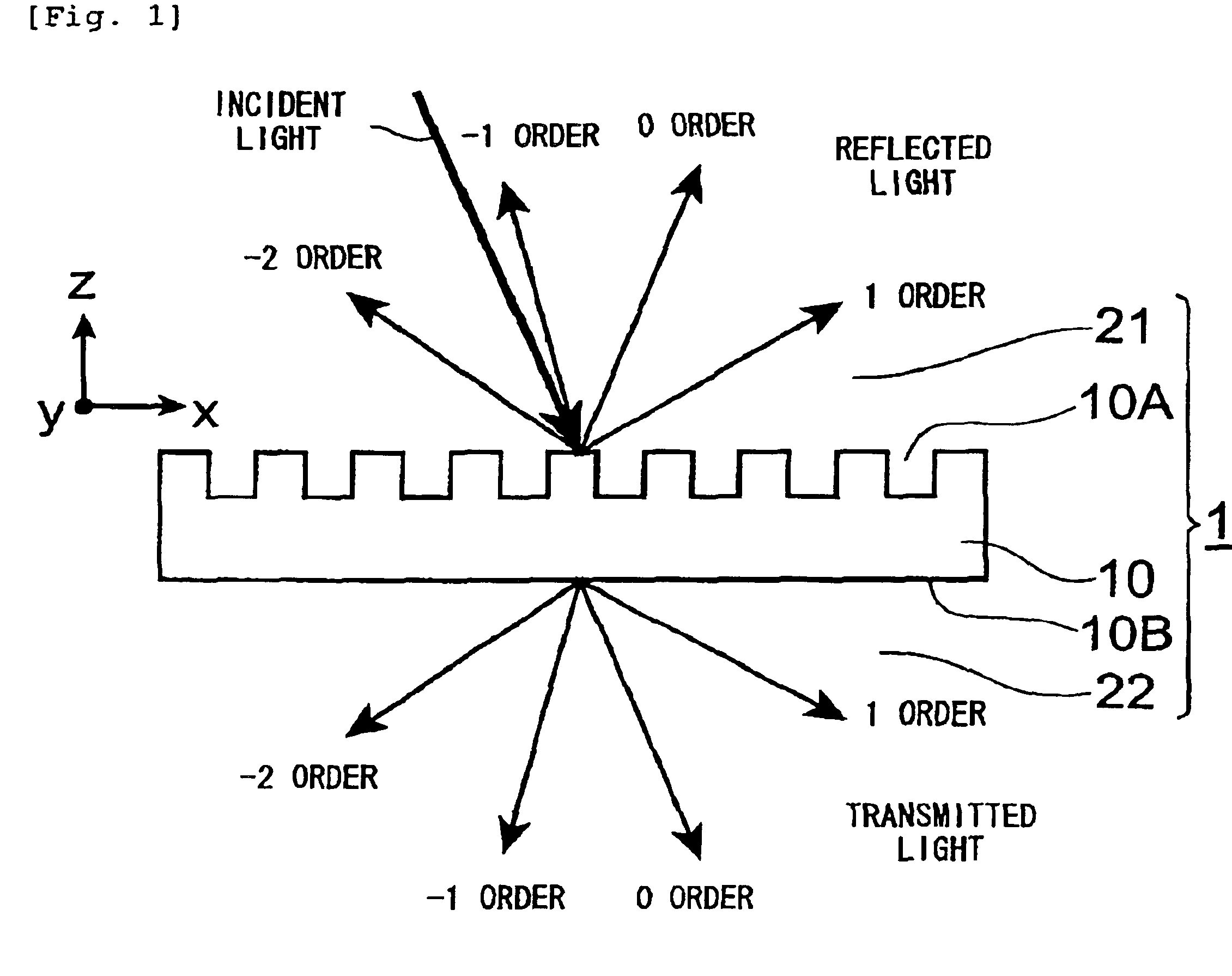
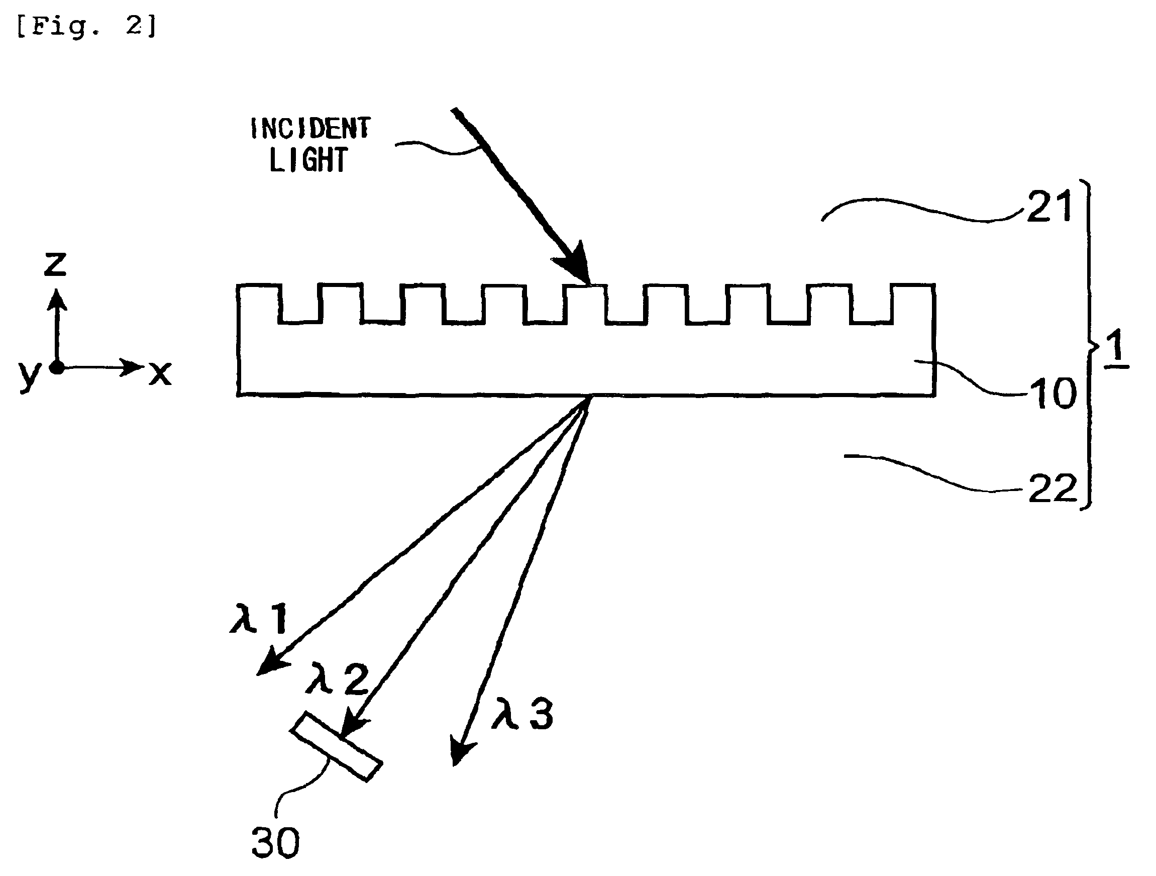
[0035]FIG. 1 is a sectional view of the diffraction grating element 1 relating to this embodiment. The diffraction grating element 1 shown in this figure has the transparent plate 10 that comprises a first surface 10A and a second surface 10B that are substantially parallel with one another. The diffraction grating element 1 has a diffraction grating formed in the first surface 10A. The diffraction grating element 1 is in contact with a surrounding medium. In FIG. 1, the first surface 10A of the diffraction grating element 1 is in contact with a medium 21 and the second surface 10B is in cont...


PUM


Abstract

The present invention provides a diffraction grating element that allows the temperature control mechanism to be dispensed with or simplified. The diffraction grating element of the present invention comprises a transparent plate having a first surface and a second surface that are substantially parallel with one another; and a diffraction grating which is formed on a first surface side with respect to the second surface and is substantially parallel with the first surface. At any temperature within a temperature range −20° C. to +80° C., the sum of the rate of change in the period per unit length of the diffraction grating with respect to a temperature change, and the temperature coefficient of the refractive index of a medium that surrounds the diffraction grating element is 0.

Description

CROSS-REFERENCE TO RELATED APPLICATION[0001]This application claims priority to Provisional Application Ser. No. 60 / 442,508 filed on Jan. 27, 2003 and Provisional Application Ser. No. 60 / 461,420 filed on Apr. 10, 2003 which are hereby incorporated by reference in their entirety.BACKGROUND OF THE INVENTION[0002]1. Field of the Invention[0003]The present invention relates to a diffraction grating element.[0004]2. Related Background of the Invention[0005]A diffraction grating element generally has a diffraction grating formed on a first surface of a transparent plate that comprises the first surface and a second surface that are parallel with one another (see Kashiko Kodate, “Development of diffractive optics and future challenges”; Japan Women's University Journal, Faculty of Science, 10th Edition, pages 7 to 24 (2002), for example). With this diffraction grating element, when, for example, light enters the first surface from a medium that is in contact with the first surface at a con...

Claims


Application Information

Patent Timeline
Patent Type & Authority Patents(United States)
IPC IPC(8): G02B5/18
CPCG01J3/02G01J3/0286G01J3/1804G02B5/18G02B5/1866G02B7/008
Inventor SHIOZAKI, MANABUSHIGEHARA, MASAKAZU
Owner SUMITOMO ELECTRIC IND LTD
Why Eureka
Try Eureka