
Locking systems for floorboards

a technology of locking system and floorboard, which is applied in the direction of roof covering, structural elements, building components, etc., can solve the problems of significantly more difficult taking up and function, and achieve the effect of facilitating the opening of the locking when taking up an installed floor, not easily visible, and easy angled downwards

Inactive Publication Date: 2005-07-19
VÄLINGE INNOVATION AB
View PDF332 Cites 112 Cited by
  • Summary
  • Abstract
  • Description
  • Claims
  • Application Information

AI Technical Summary

Benefits of technology

The present invention aims to provide a locking system for floors that addresses the problems of traditional glued floors and thin floor structures. The system includes locking surfaces with a high locking angle and strength, as well as a horizontal joint system that is openable and includes guiding parts for positioning of the floorboards. The locking element has an operative looking surface in its upper part, which facilitates taking up an installed floor by upward angling. The invention is based on the understanding that these problems must be solved with a locking system that addresses the needs of perpendicular locking surfaces that are easy to open.

Problems solved by technology

The drawback of this design of the locking element is the taking-up function, which is a vital part in most mechanical locking systems.
If the locking angle is greater than the clearance angle, the parts of the locking system will overlap each other in upward angling, which makes the taking-up considerably more difficult.

Method used


Image

  • Locking systems for floorboards
  • Locking systems for floorboards
  • Locking systems for floorboards

Examples


Embodiment Construction

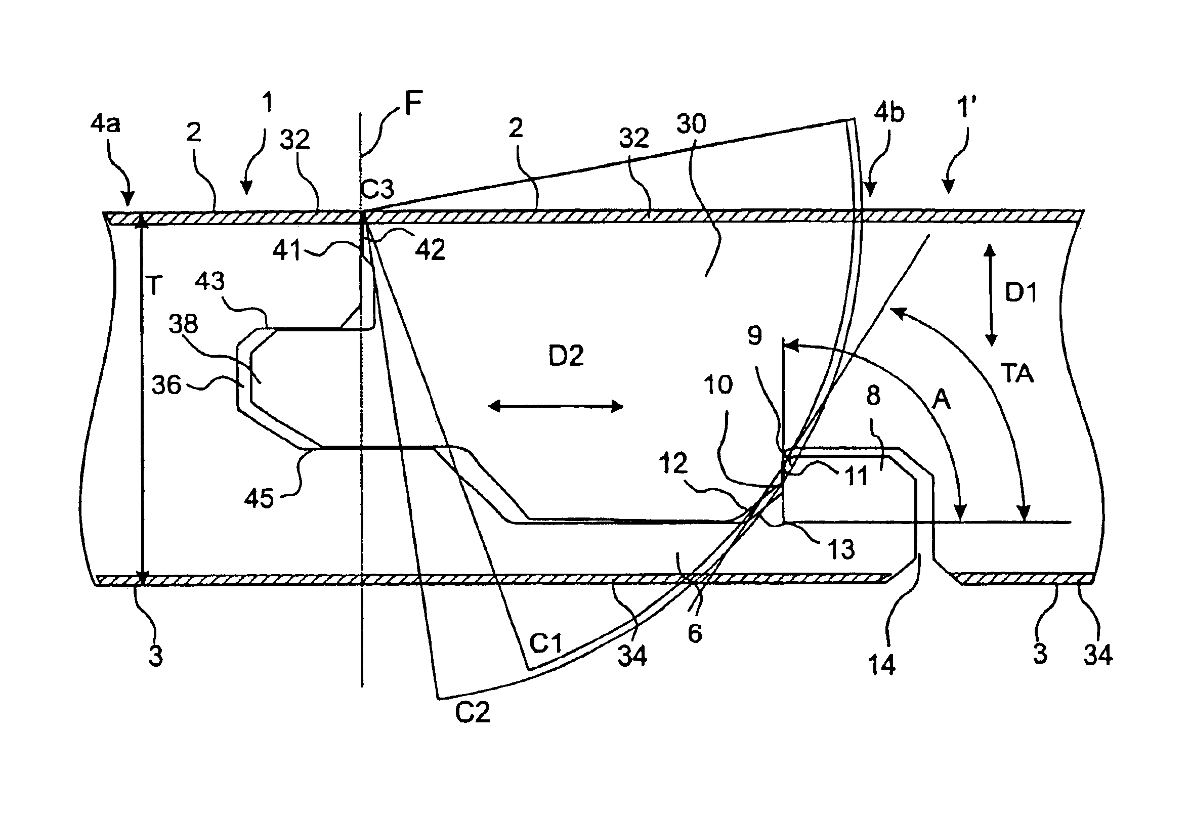
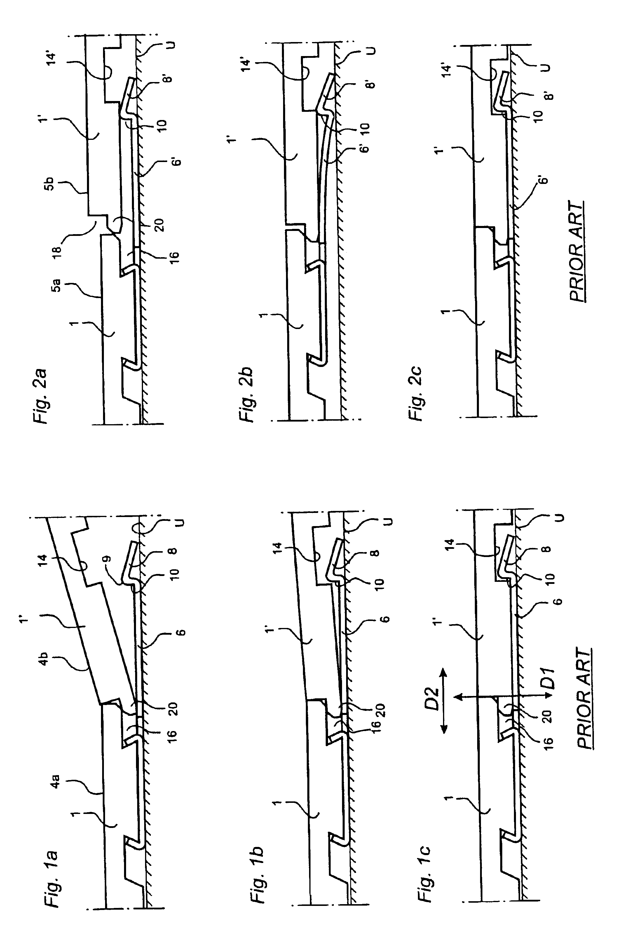
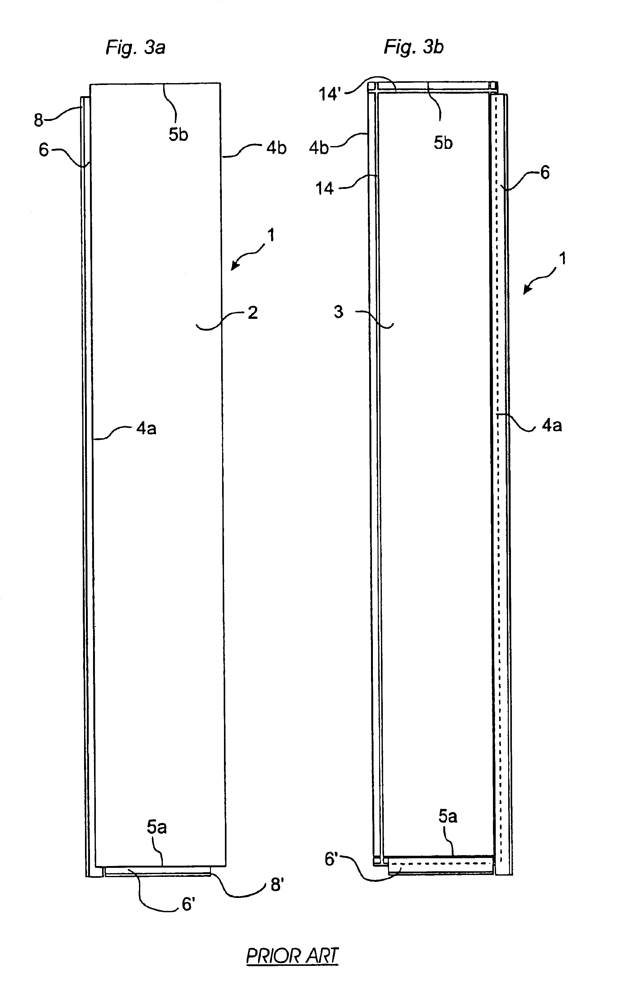
[0052]Prior to the description of preferred embodiments, with reference to FIG. 5, a detailed explanation will first be given of the most important parts in a strip lock system.

[0053]The invention can be applied in joint systems with a worked strip which is made in one piece with the core of the board, or with a strip which is integrated with the core of the board but which has been made of a separate material, for instance aluminium. Since the worked embodiment, where strip and core are made of the same material, constitutes the greatest problem owing to higher friction and poorer flexibility, the following description will focus on this field of application.

[0054]The cross-sections shown in FIG. 5 are hypothetical, not published cross-sections, but they are fairly similar to the locking system of the known floorboard “Fiboloc®” and to the locking system according to WO 9966151. Accordingly, FIG. 5 does not represent the invention but is only used a starting point of a description ...


PUM


Abstract

The invention relates to a locking system for mechanical joining of floorboards (1, 1′), a floorboard having such a locking system and a flooring made of such floorboards. The locking system has mechanical cooperating means (36, 38; 6, 8, 14) for vertical and horizontal joining of adjoining floorboards. The means for horizontal joining about a vertical plane (F) comprise a locking groove (14) and a locking strip (16) which is located at opposite joint edge portions (4a, 4b) of the floorboard (4). The locking strip (6) projects from the joint plane (F) and has an upwards projecting locking element (8) at its free end. The locking groove (14) is formed in the opposite joint edge portion (4a) of the floorboard at a distance from the joint plane (F). The locking groove (14) and the locking element (8) have operative locking surfaces (10, 11). The locking surfaces are essentially plane and spaced from the upper side of the projecting strip and inside the locking groove and make a locking angle (A) of at least 50° to the upper side of the board. Moreover the locking groove has a guiding part (12) for cooperation with a corresponding guiding part (6) on the locking element (8).

Description

[0001]This application is a continuation of U.S. application Ser. No. 09 / 954,180, filed on Sep. 18, 2001, U.S. Pat. No. 6,715,253 which was a continuation of International Application No. PCT / SE01 / 00779, filed on Apr. 9, 2000, which claims the priority of 0001325-0 filed in Sweden on Apr. 10, 2000.TECHNICAL FIELD[0002]The invention generally relates to the field of mechanical locking of floorboards. The invention relates to an improved locking system for mechanical locking of floorboards, a floorboard provided with such an improved locking system, and a flooring made of such mechanically joined floorboards. The invention generally relates to an improvement of a locking system of the type described and shown in WO 9426999 and WO 9966151.[0003]More specifically, the invention relates to a locking system for mechanical joining of floorboards of the type having a core and preferably a surface layer on the upper side of the core and a balancing layer on the rear side of the core, said lo...

Claims


Application Information

Patent Timeline
Patent Type & Authority Patents(United States)
IPC IPC(8): E04F15/04E04F15/02
CPCE04F15/02E04F15/04E04F2201/0115E04F2201/042E04F2201/0153E04F2201/023E04F2201/026E04F2201/0138
Inventor PERVAN, DARKO
Owner VÄLINGE INNOVATION AB
Learn More