Seal for high-pressure pumping system

Inactive Publication Date: 2005-07-19
DIONEX CORP
View PDF29 Cites 28 Cited by
  • Summary
  • Abstract
  • Description
  • Claims
  • Application Information

AI Technical Summary

Benefits of technology

[0018]Another object of the present invention is to provide an improved seal designed and configured to reduce, minimize and/or prevent O-ring abrasion.
[0019]It is

Problems solved by technology

Disadvantageously, the configuration of conventional seals can lead to abrasion and granulation of O-ring 38.
Such movement of O-ring 38 causes the O-ring to chafe against inner cavity wall 41 thus causing abrasion, granulation and/or other wear of the O-ring, which in turn, may lead to contamination of the working fluid and/or the mobile phase flowing through the pump.
In particular, O-ring 38 may be formed of a fluoropolymer material and the introduction of such particles into the flow stream through the pump can lead to fluorine contamination of the chromatography system utilizing such a conventional seal.
Disadvantageously, pumped fluid may contact the energizing internal component either directly or indirectly under normal operating conditions.
Stainless-steel, however, is not suitable for use with acidic aqueous pumped fluids as such fluids may cause corrosion of

Method used


Image

  • Seal for high-pressure pumping system
  • Seal for high-pressure pumping system
  • Seal for high-pressure pumping system

Examples


Embodiment Construction

[0035]Reference will now be made in detail to the preferred embodiments of the invention, examples of which are illustrated in the accompanying drawings. While the invention will be described in conjunction with the preferred embodiments, it will be understood that they are not intended to limit the invention to those embodiments. On the contrary, the invention is intended to cover alternatives, modifications and equivalents, which may be included within the spirit and scope of the invention as defined by the appended claims.

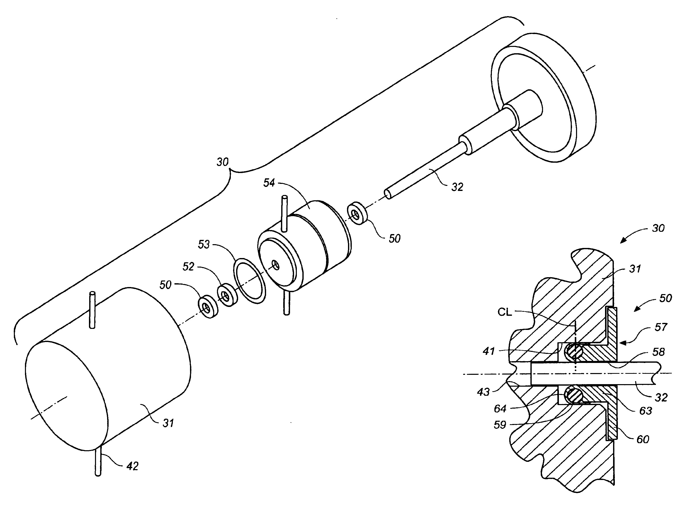
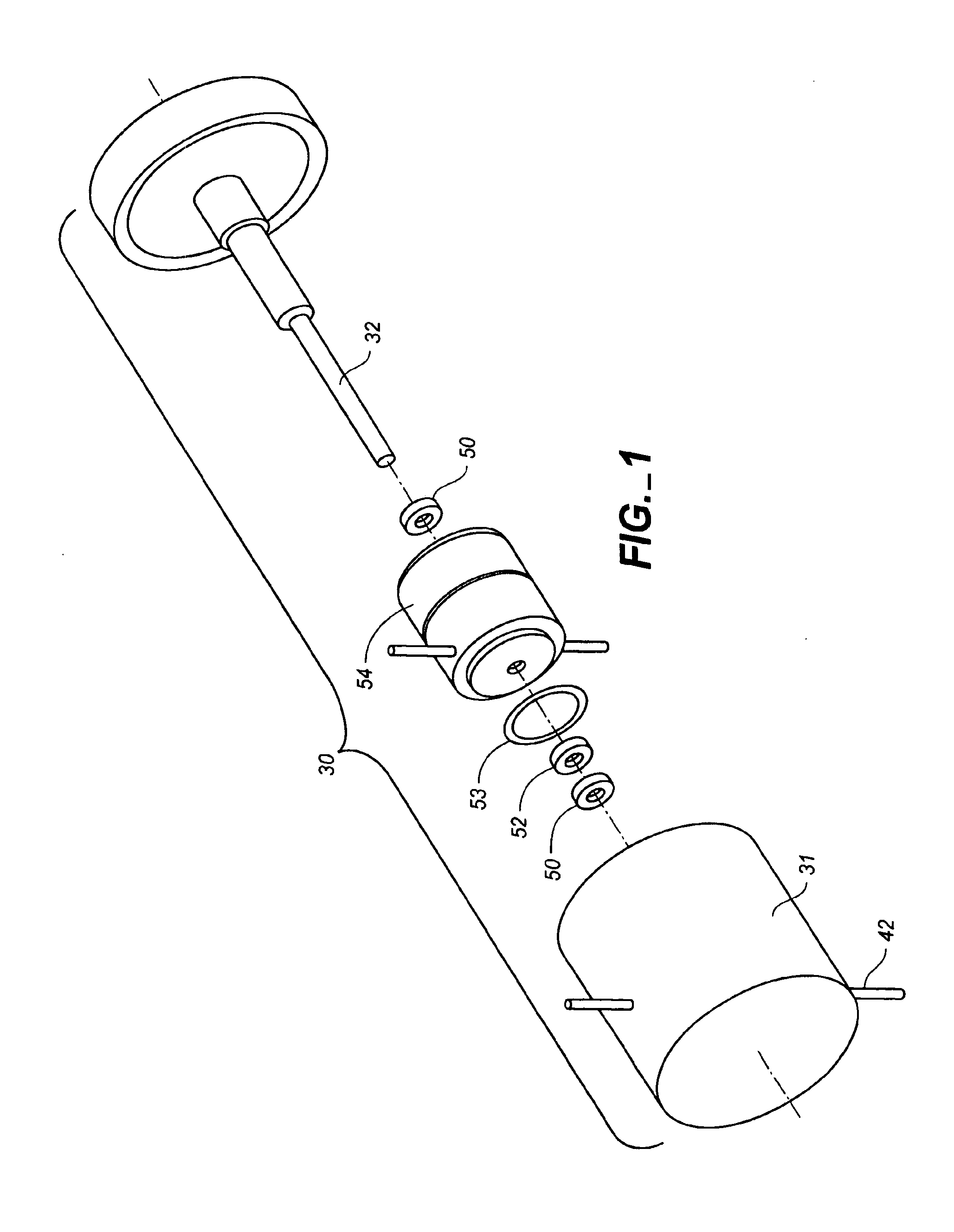
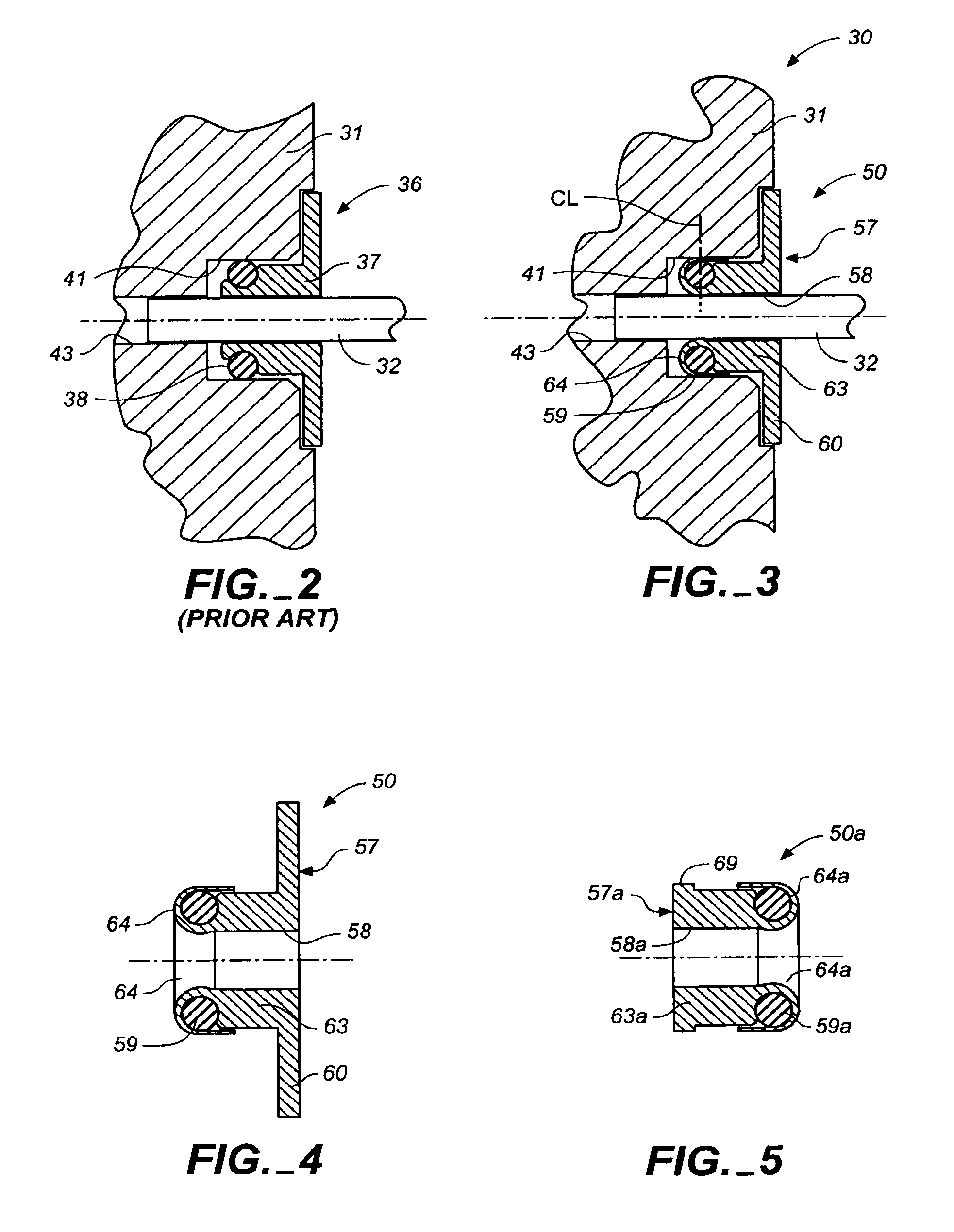
[0036]Turning now to the drawings, wherein like components are designated by like reference numerals throughout the various figures, attention is directed to FIG. 3 which illustrates an HPLC pump 30 with which a toroidally-formed wrap-around seal 50 can be used in accordance with the present invention. One should appreciate that seal 50 is suitable for use as a pump seal for all high-pressure pumping systems in accordance with the present invention.

[0037]With re...


PUM


Abstract

A high-pressure pumping system including an energizing seal component having an aperture extending therethrough and a seal jacket component having a base and a toroidally-shaped flared membrane extending from the base. The body and the flared membrane are monolithically formed of an inert polymeric seal material. The flared membrane extends through the aperture and encircles the energizing seal component to isolate the energizing seal component from fluid of the pumping system. The flared membrane may extend axially from the body and encircle the energizing seal component. The flared membrane may encircle the energizing seal component and overlaps a portion of the base. The seal jacket component may be formed around the energizing seal component. The seal jacket component may include a flange extending radially outwardly from the base.

Description

BACKGROUND OF THE INVENTION[0001]1. Field of the Invention[0002]The present invention relates to a new and improved flange seal. In particular, the present invention relates to flange seals suited for use with high-pressure devices such as a chromatography pump.[0003]2. Description of Related Art[0004]High-pressure liquid chromatography (HPLC) generally requires the components of a sample to be separated or analyzed be dissolved in a mobile phase liquid, termed an eluent, and conveyed by that liquid to a stationary phase, that is, a chromatography column. HPLC eluent delivery systems are used to supply the liquid and deliver the liquid, with dissolved sample, to the column. Selected pressures ranging from substantially atmospheric pressure to pressures on the order of thousands of pounds per square inch are common to force the liquid into the column. Specially designed HPLC pumps are used to withstand extreme pressures and to deliver the liquid at precisely controlled flow rates in ...

Claims


Application Information

Patent Timeline
IPC IPC(8): F04B53/16F04B53/00F16J15/10
CPCF04B53/164F16J15/104F16J15/16
Inventor PROPER, GEORGE N.
Owner DIONEX CORP
Why Eureka
Try Eureka