
Temperature sensor and method for manufacturing the same

a temperature sensor and liquid technology, applied in the direction of resistor housing/enclosement/embedding, heat measurement, instruments, etc., can solve the problems of b>140/b>/i>b /i>may be deformed, and achieve low short-circuit possibility, no cracks, and high reliability

Active Publication Date: 2005-07-19
SHIBAURA ELECTRONICS CO LTD
View PDF13 Cites 24 Cited by
  • Summary
  • Abstract
  • Description
  • Claims
  • Application Information

AI Technical Summary

Benefits of technology

The present invention provides a temperature sensor with high reliability. Specifically, the sensor has a low possibility of short-circuit and no crack in the mold portion. The method for manufacturing the temperature sensor includes the steps of forming a casing, integrating an insert portion with the casing, connecting outside wires to a temperature detector, inserting the outside wires into the holes, and filling with resin to form a mold portion. The technical effects of the invention are improved reliability and reduced manufacturing costs.

Problems solved by technology

However, the insulation tube 140b may be deformed in some cases such as sudden temperature change.

Method used


Image

  • Temperature sensor and method for manufacturing the same
  • Temperature sensor and method for manufacturing the same
  • Temperature sensor and method for manufacturing the same

Examples


Embodiment Construction

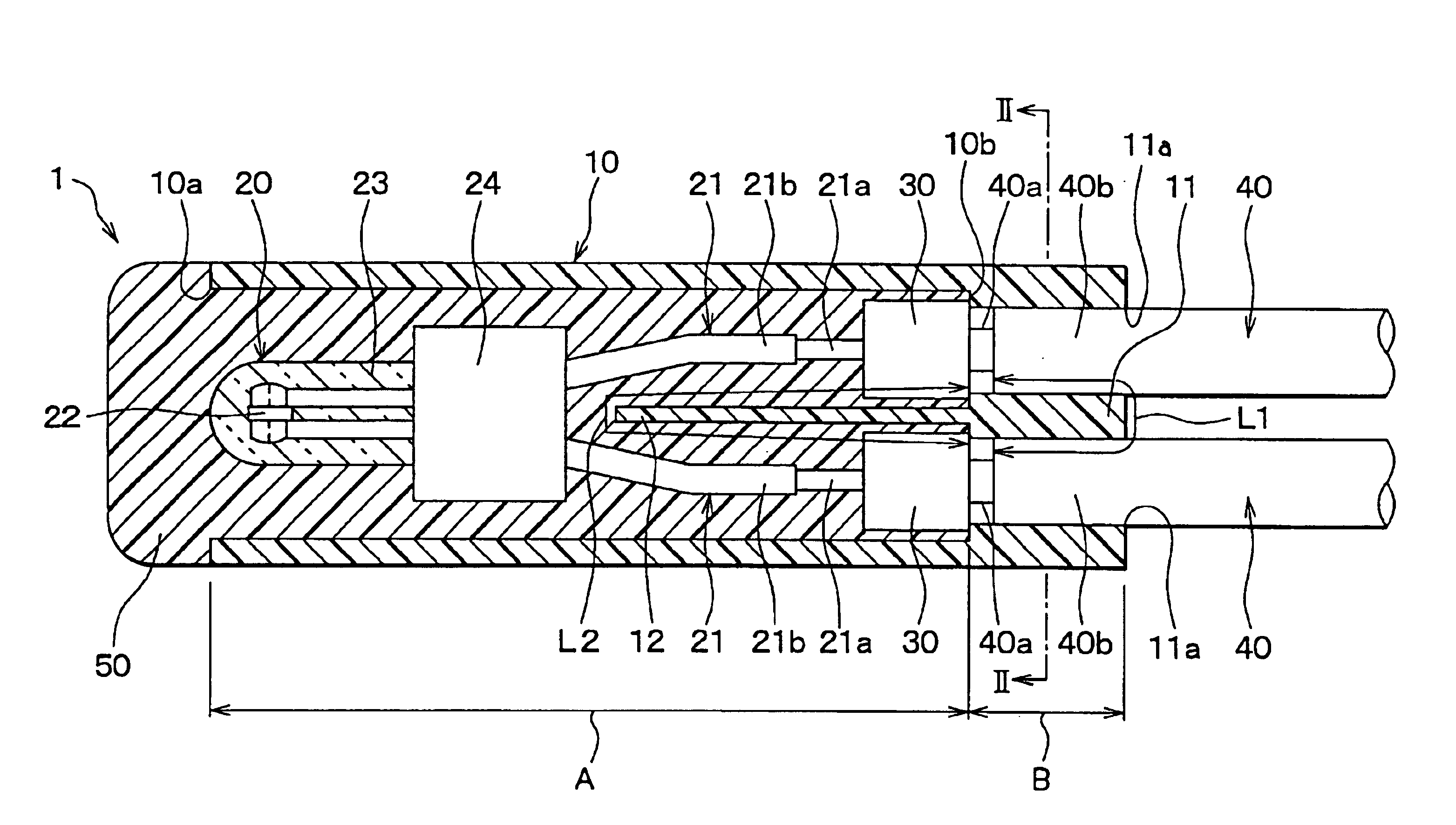
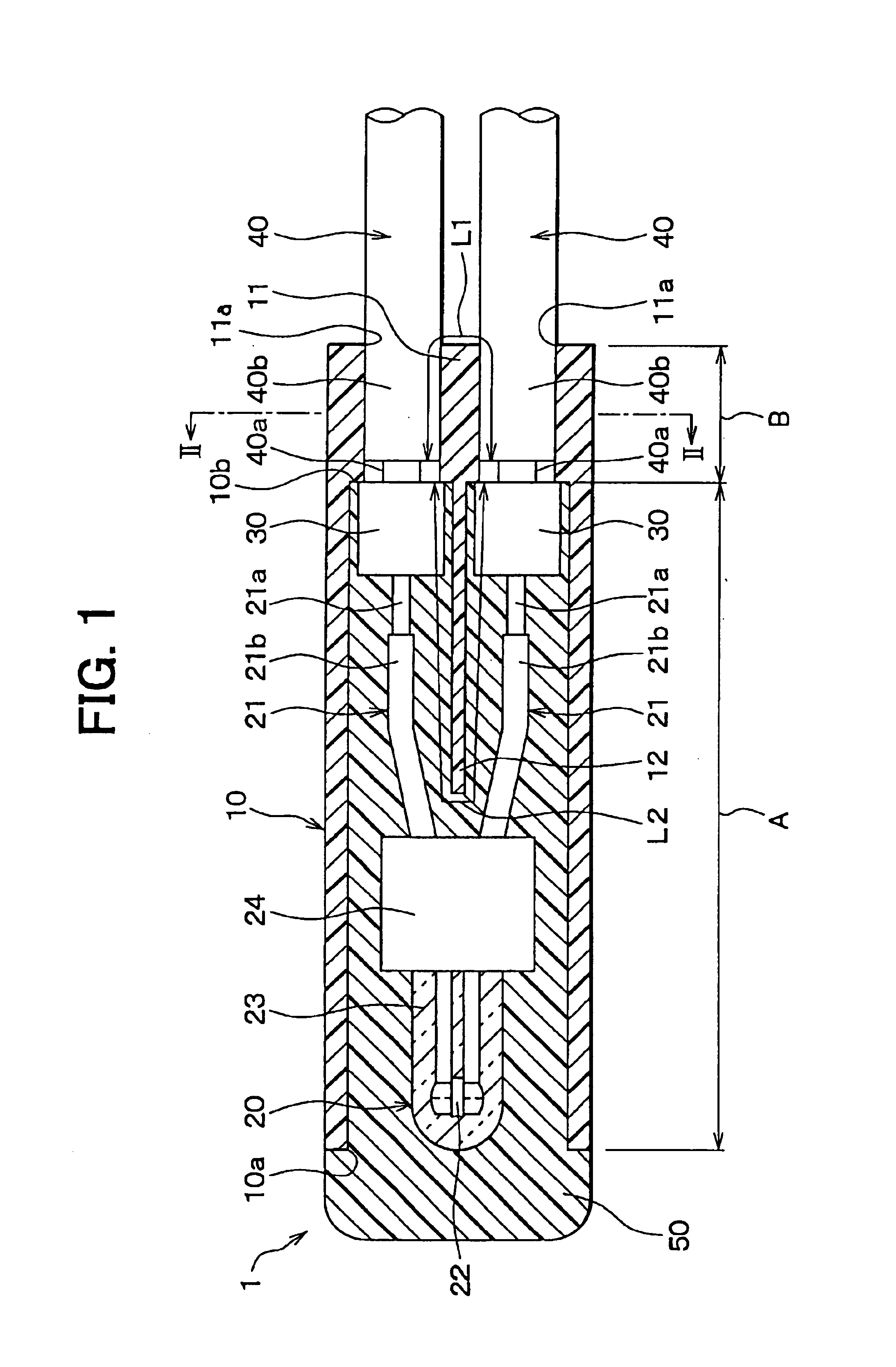
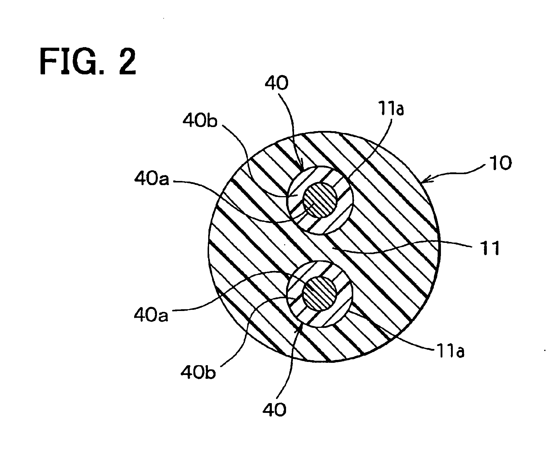
[0018]A temperature sensor 1 for detecting temperature of fluid according to a preferred embodiment of the present invention is shown in FIG. 1. The sensor 1 is suitably used for detecting temperature of fuel supplying to an engine of a vehicle. The sensor 1 is mounted in the fuel, and detects the temperature of the fuel. Specifically, the sensor 1 is mounted on a fuel pump disposed in a fuel tank of the vehicle.

[0019]The sensor 1 includes a casing 10 having a cylindrical shape. The casing 10 is made of resin such as poly phenylene sulfide (i.e., PPS) resin or poly oxy methylene (i.e., POM) resin. Part of the casing 10, which is shown as A in FIG. 1, is defined as the first part A. The other part of the casing 10, which is shown as B in FIG. 1, is defined as the second part B. The first part A is disposed on the left side of the casing 10, i.e., the top end side of the sensor 1. The second part B is disposed on the right side of the casing 10, i.e., the middle portion of the sensor ...


PUM

PropertyMeasurementUnit
temperatureaaaaaaaaaa
cylindrical shapeaaaaaaaaaa
distances L3aaaaaaaaaa

Abstract

A temperature sensor includes a casing having a first part and a second part, a temperature detector for detecting temperature of fluid and a pair of outside wires connecting to the temperature detector. The casing further includes a mold portion and an insert portion. The mold portion is disposed in the first part of the casing. The insert portion is disposed in the second part of the casing, and includes a pair of holes for inserting the outside wires therein. The temperature detector is disposed in the first part of the casing. Each outside wire extends from the second part of the casing to an outside of the casing through the hole.

Description

CROSS REFERENCE TO RELATED APPLICATION[0001]This application is based on Japanese Patent Application No. 2003-6903 filed on Jan. 15, 2003, the disclosure of which is incorporated herein by reference.FIELD OF THE INVENTION[0002]The present invention relates to a temperature sensor for detecting temperature of liquid and a method for manufacturing the same.BACKGROUND OF THE INVENTION[0003]A temperature sensor for detecting temperature of liquid according to a prior art is disclosed in Japanese Unexamined Utility Model Application Publication No. H03-39125. This sensor 100 is shown in FIG. 3. The sensor 100 is disposed in the liquid so as to detect the temperature of the liquid. The sensor 100 includes a temperature detector 120 connecting to a pair of electric wires 140. The wires 140 extend from a casing 110 of the sensor 100 to the outside of the casing 110. The wire 140 is composed of a lead wire 140a coated with an insulation tube 140b. The wire 140 connects to the detector 120 at...

Claims


Application Information

Patent Timeline
Patent Type & Authority Patents(United States)
IPC IPC(8): G01K13/02G01K13/00
CPCG01K13/02G01K2013/026Y10T29/49117Y10T29/49176Y10T29/49085Y10T29/49007Y10T29/49087G01K13/026
Inventor HOSHISASHI, AKIHIKOKAWASHIMA, SEIZABUROU
Owner SHIBAURA ELECTRONICS CO LTD
Learn More