Capsule endoscope

a technology of endoscope and capsule, which is applied in the field of endoscope of capsule, can solve the problems of large capsule size, design requires additional labor, and the oval dome size to become larger, and achieves the effect of easy and inexpensive manufacturing

Active Publication Date: 2005-07-19
OLYMPUS CORP
View PDF7 Cites 122 Cited by
  • Summary
  • Abstract
  • Description
  • Claims
  • Application Information

AI Technical Summary

Benefits of technology

[0006]The present invention relates to a capsule endoscope that is swallowed in order to examine interior regions of a living body. More particularly, the present invention provides a small-sized capsule endoscope having a transparent cover that is easy and inexpensive to manufacture, and which makes it difficult for undesirable light from the illumination means to enter the objective optical system.

Problems solved by technology

Since each element should be adjusted in position, this design requires additional labor.
This causes the size of the oval dome to become larger, which disadvantageously requires that the capsule be larger.
However, increasing the size of the capsule is undesirable because it becomes difficult, even painful, to swallow such an encapsulated endoscope.
Thus, the advantage of using a capsule endoscope is lost.

Method used


Image

  • Capsule endoscope
  • Capsule endoscope
  • Capsule endoscope

Examples


embodiment 1

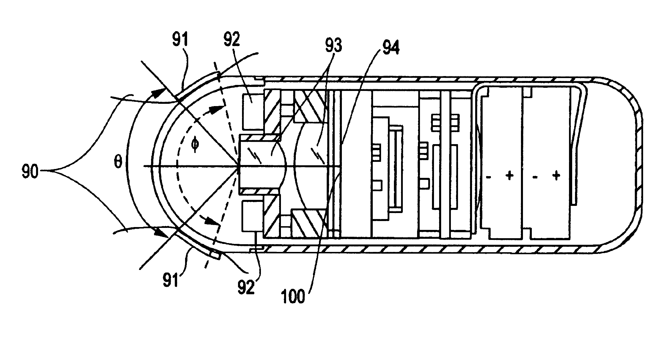
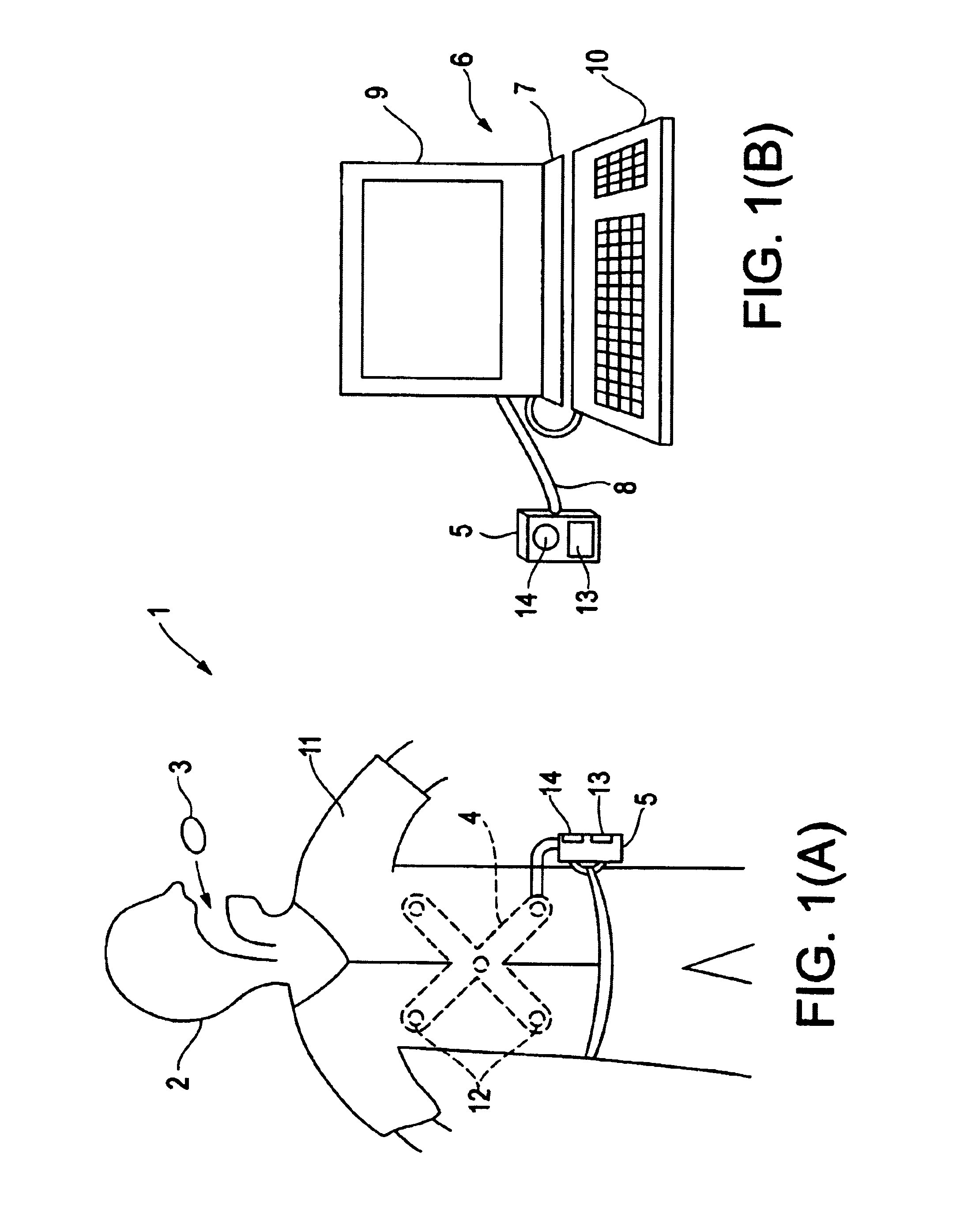
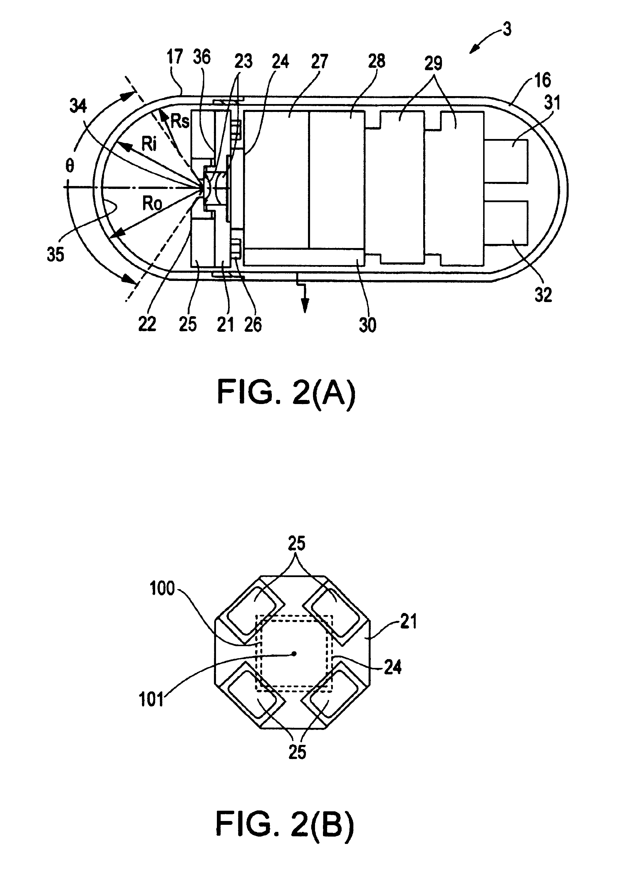
[0037]Embodiment 1 will be described with reference to FIGS. 1(A)-4(B). FIGS. 1(A) and 1(B) show a capsule endoscope system which uses a capsule endoscope according to Embodiment 1 of the present invention. FIG. 2(A) is a section view showing the internal structure of the capsule endoscope. FIG. 2(B) is an illustration showing the positional relationship between the image detecting means and the illumination means when viewing the capsule endoscope axially from the object side. FIG. 3 is an enlarged view of the objective optical system. FIGS. 4(A) and 4(B) show the effects of an objective optical system that uses a semi-spherical window, with FIG. 4(A) illustrating the situation of the illuminating light being positioned at the center of curvature of the semi-spherical transparent cover, and with FIG. 4(B) illustrating the situation of the illuminating light being positioned somewhere else.

[0038]As shown in FIG. 1(A), a capsule endoscope system 1 uses a capsule endoscope 3 according...

embodiment 2

[0074]Embodiment 2 of the present invention will now be described with reference to FIG. 5. FIG. 5 is a schematic view showing the structure of the capsule endoscope 3B of Embodiment 2. The thickness of the transparent cover 17B in this embodiment is no longer uniform. Instead, the transparent cover 17B is thicker on axis and tapers so as become thinner toward the peripheral regions of the field of view. The transparent cover 17B is provided with an inner surface having a radius of curvature Ri, for example, equal to 5.5 mm within the visual field angle θ, with the center of curvature coinciding with the center of the entrance pupil 34 of the objective optical system 23.

[0075]On the other hand, the outer surface of the transparent cover 17B has a radius of curvature Ro, for example, equal to 5.5 mm within the visual field angle θ. The center of curvature of the outer surface is located on the optical axis but is positioned on the object side of the entrance pupil position 34 of the ...

embodiment 3

[0082]FIG. 10(A) is a cross-sectional view of an capsule endoscope 51 of Embodiment 3 of the present invention. FIG. 10(B) is an illustration showing the positional relationship between the illumination means and the image detecting element when viewing the capsule endoscope axially from the object side. Referring to FIG. 10(A), the capsule endoscope 51 includes a transparent front cover 52 that has a cylinder form with a semi-spherical front end and a rear cover 53 which also is shaped as a cylinder that has a semi-spherical rear end. The rear end of the transparent front cover 52 and the front end of the rear cover are fitted to each other and sealed so as to create a watertight capsule container in which an objective optical system 54 and other elements are housed.

[0083]The objective optical system 54 is formed of a first lens supported by a first lens frame 55 and a second lens supported by a second lens frame 56, and is positioned along the axis of symmetry of the capsule with ...


PUM


Abstract

A capsule endoscope is disclosed that includes means for illuminating an object, means for imaging the object, and a transparent cover having a center of curvature. The transparent cover covers the illumination means and the imaging means, and the imaging means includes an objective optical system and an image detecting element. The illumination means is positioned relative to the image detecting element, as viewed axially from the object side of the capsule endoscope, so that an area that is symmetrically positioned about the optical axis of the objective optical system from a light emitting area of the illumination means overlaps an area of the image detecting element, but does not overlap any areas of the image detecting element that are used for image detection.

Description

CROSS REFERENCE TO RELATED APPLICATION[0001]This application claims the benefit of foreign priority from Japanese Patent Application No. 2002-064016, filed Mar. 8, 2002, the contents of which are hereby incorporated by reference.BACKGROUND OF THE INVENTION[0002]Endoscopes have recently come into extensive use in the medical and industrial fields. Recent medical endoscopes do not have an insertion member and there is no longer an insertion process. These are medical endoscopes are encapsulated within a capsule, which a patient can swallow. This eliminates the pain associated with insertion of prior art endoscopes that have an insertion member. Examples of capsule endoscopes include, for instance, those disclosed in the Japanese Laid-Open Patent Application 2001-91860 and the patent publication PCT WO 00 / 76 391 A1.[0003]The prior art capsule endoscope disclosed in Japanese Laid-Open Patent Application 2001-91860 is provided with an objective lens and an illumination means consisting o...

Claims


Application Information

Patent Timeline
Patent Type & Authority Patents(United States)
IPC IPC(8): A61B5/05A61B5/00A61B5/07A61B1/00A61B1/05
CPCA61B1/00036A61B1/041A61B1/0684A61B1/00016A61B1/0011A61B5/0031
Inventor YOKOI, TAKESHIHASEGAWA, AKIRAMATSUMOTO, SHINYASUZUKI, TAKAYUKISEGAWA, HIDETAKETAKIZAWA, HIRONOBU
Owner OLYMPUS CORP
Why Eureka
Try Eureka