Surface electrode multiple mode operation

a surface electrode and multiple-mode technology, applied in the field of tissue ablation devices, can solve the problems of disadvantages of using multiple-mode electrode arrangements, other tissue structures of patients and treating personnel, and the risk of accidental contact of electrodes with other tissue structures, so as to minimize the risk of inadvertent ablation of healthy tissue

Inactive Publication Date: 2005-07-19
BOSTON SCI SCIMED INC
View PDF9 Cites 276 Cited by
  • Summary
  • Abstract
  • Description
  • Claims
  • Application Information

AI Technical Summary

Benefits of technology

[0011]The surface electrode may optionally comprise insulation to minimize inadvertent ablation of healthy tissue. For example, the surface of the base from which the needle electrodes extend may be electrically insulated. Or the surface electrode may further comprise a plurality of electrically insulating sleeves extending from the surface of the base, wherein the insulating sleeves encompass portions of the respective needle electrodes. The insulating sleeves may be optionally extendable from the surface of the base an adjustable length. By way of non-limiting example, the adjustability of the insulating sleeves allows the depth at which healthy tissue is protected to be adjusted.

Problems solved by technology

Difficulties have arisen in using the multiple electrode arrangements of U.S. Pat. No. 6,379,353 in treating tumors that lay at or near the surface of an organ, such as the liver.
Such exposure of the needle tips outside the tissue to be treated is disadvantageous in a number of respects.
First, the presence of active electrodes outside of the confinement of the organ being treated subjects other tissue structures of the patient as well as the treating personnel to risk of accidental contact with the electrodes.
Moreover, the presence of all or portions of particular electrodes outside of the tissue being treated can interfere with proper heating of the tissue and control of the power supply driving the electrodes.
While it would be possible to further penetrate the needle electrode into the treated tissue, such placement can damage excessive amounts of healthy tissue.
Although the ablation assembly illustrated in FIG. 1 is generally useful in ablating superficially oriented tumors, it cannot be used to efficiently and safely ablate such tumors in all circumstances.
For example, if the tumor is quite close to the surface of the tissue, placement of the needle electrodes without exposing any metallic surface can be difficult.
Also, it may not be practical to use the probe assembly when the tumors are quite shallow.
Efficient ablation of the tumor, however, may not be achieved if the tumor has a non-uniform thickness.

Method used


Image

  • Surface electrode multiple mode operation
  • Surface electrode multiple mode operation
  • Surface electrode multiple mode operation

Examples


Embodiment Construction

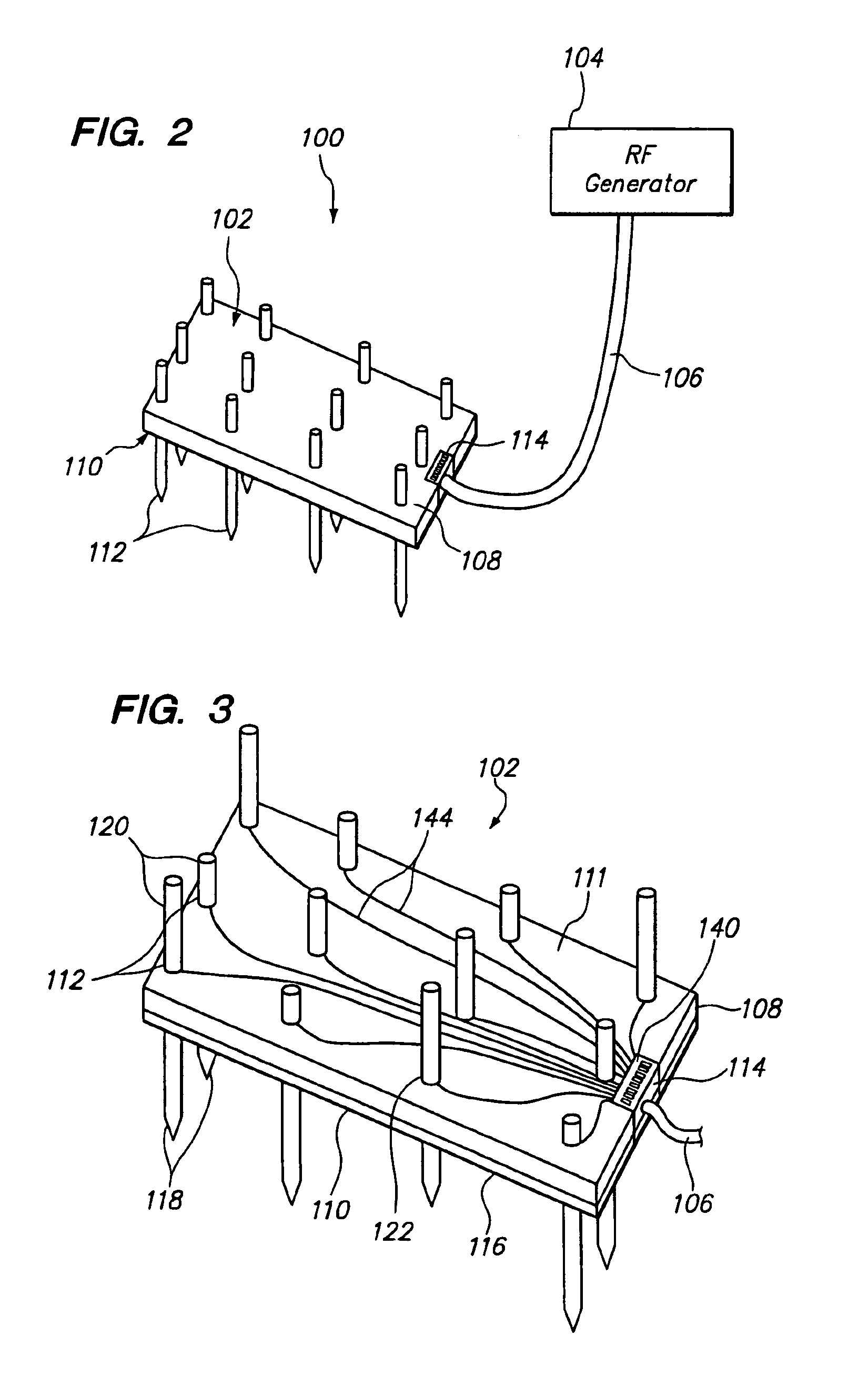
[0038]FIG. 2 illustrates a tissue ablation system 100 constructed in accordance with a preferred embodiment of the present invention. The tissue ablation system 100 generally comprises a surface electrode 102, which is configured to be applied to the surface of tissue, e.g., an organ, in order to ablate target tissue therein, and a radio frequency (RF) generator 104 configured for supplying RF energy to the surface electrode 102 via a cable 106 in a controlled manner. In the embodiment illustrated in FIG. 2, only one surface electrode 102 is shown. As will be described in further detail below, however, multiple surface electrodes 102 can be connected to the RF generator 104 depending upon the specific ablation procedure that the physician selects.

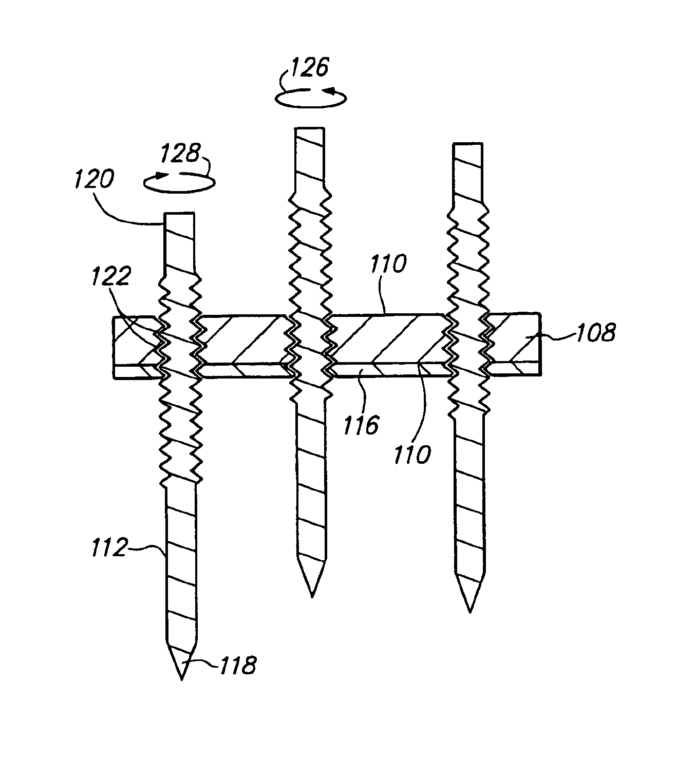
[0039]Referring further to FIG. 3, the surface electrode 102 generally comprises a base 108 having a flat surface 110, an array of needle electrodes 112 extending from the surface 110 of the base 108, and an electrical interface 114 for ele...


PUM


Abstract

A surface electrode for ablating tissue is provided. The surface electrode comprises a base, a plurality of tissue penetrating needle electrodes extending from the surface of the base an adjustable distance, and an electrical interface coupled to the plurality of needle electrodes. The adjustability of the needle electrodes allows the depth that the needle electrodes penetrate through tissue to be adjusted.

Description

FIELD OF THE INVENTION[0001]The field of the invention relates generally to the use of ablation devices for the treatment of tissue, and more particularly, RF ablation devices for the treatment of tumors.BACKGROUND OF THE INVENTION[0002]The delivery of radio frequency (RF) energy to target regions within tissue is known for a variety of purposes. Of particular interest to the present invention, RF energy may be delivered to diseased regions in target tissue for the purpose of causing tissue necrosis. For example, the liver is a common depository for metastases of many primary cancers, such as cancers of the stomach, bowel, pancreas, kidney, and lung. Electrosurgical probes with deploying electrode arrays have been designed for the treatment and necrosis of tumors in the liver and other solid tissues. See, for example, the LeVeen™ Needle Electrode available from Boston Scientific Corporation, which is constructed generally in accord with U.S. Pat. No. 6,379,353, entitled “Apparatus a...

Claims


Application Information

Patent Timeline
Patent Type & Authority Patents(United States)
IPC IPC(8): A61B18/14A61B18/00
CPCA61B18/1477A61B2018/00023A61B2018/00029A61B2018/00083A61B2018/0016A61B2018/00196A61B2018/1425A61B2018/143A61B2018/1475
Inventor KELLY, AMY C.LANDREVILLE, STEVEN K.GARABEDIAN, ROBERT J.
Owner BOSTON SCI SCIMED INC
Why Eureka
Try Eureka