Method and apparatus for identifying composite defective pixel map

a composite and defective technology, applied in the field of xray detectors, can solve the problems of reducing diagnostic usefulness, affecting the diagnostic affecting the detection accuracy of the detector, so as to achieve the effect of improving diagnostic usefulness, and reducing the detection accuracy

Inactive Publication Date: 2005-07-19
GE MEDICAL SYST GLOBAL TECH CO LLC
View PDF10 Cites 39 Cited by
  • Summary
  • Abstract
  • Description
  • Claims
  • Application Information

AI Technical Summary

Problems solved by technology

The range of offset values and gain correction factors is limited and therefore, not surprisingly, at least some fraction of detector pixels generate signals that cannot be corrected to reflect actual X-ray intensity using the offset values and gain factors.
Nevertheless, because signal intensity from bad pixels is either independent of X-ray exposure or depends on X-ray exposure in a way that is different than signal intensities generated by adjacent good pixels, the effects of bad pixels are visually noticeable as artifacts (e.g., pixels, lines etc) in resulting images and hence degrade diagnostic usefulness.
It is also known that detector elements have varying useful lives and that at least a percentage of detector pixels that are initially good when shipped by a manufacturer will become bad during detector use.
While bad pixel correction processes clearly result in diagnostically more useful images, at some point the number and/or pattern of bad pixels exceeds minimum detector performance needed to ensure diagnostic quality images and the detector itself has to be repaired or replaced.
Thus, for instance, when 10% of detector pixels are bad, the detector may be considered defective.
As another instance, where a detectors

Method used


Image

  • Method and apparatus for identifying composite defective pixel map
  • Method and apparatus for identifying composite defective pixel map
  • Method and apparatus for identifying composite defective pixel map

Examples


Embodiment Construction

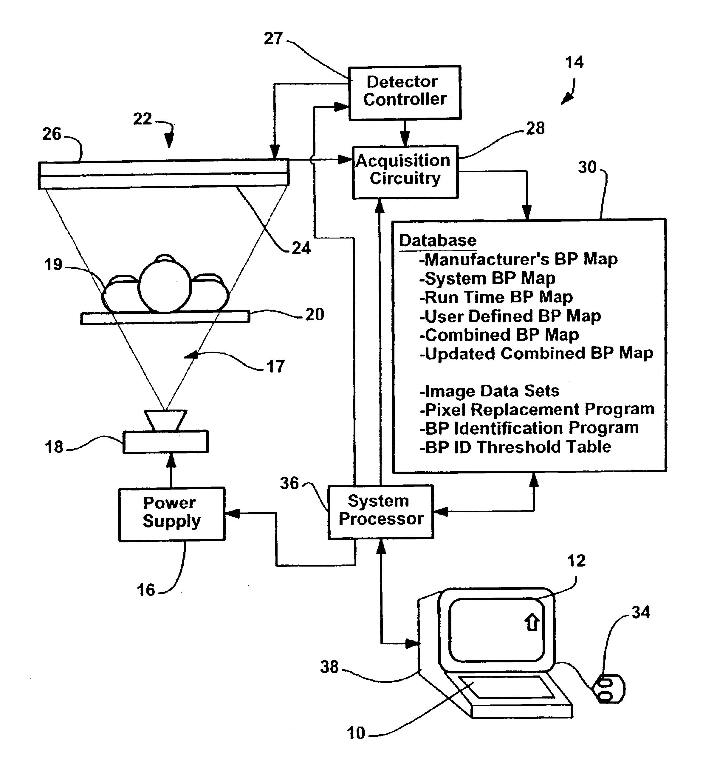
[0033]Referring now to the drawings, and more specifically, referring to FIG. 1, the present invention will be described in the context of exemplary X-ray imaging system 14 which includes an X-ray source 18, a large area solid state X-ray detector 22, a patient support table 20, a power supply 16, a detector controller 27, acquisition circuitry 28, a system processor 36, a database 30, and a user interface generally identified by numeral 38. As illustrated, when X-ray source 18 is excited by power supply 16, source 18 emits an X-ray beam 17. Source 18 and detector 22 are juxtaposed on opposite sides of an imaging area such that the X-ray beam 17 emanating from source 18 is directed toward a detecting surface of detector 22 and subtends the detecting surface.

[0034]Patient support table 20 is generally positioned within X-ray beam 17 such that, when a patient 19 is positioned for support on table 20 within the imaging area, the patient or, at least, a portion of the patient of interes...


PUM


Abstract

An apparatus for use with a detector system including a solid state flat panel detector and an image processor, the detector including a plurality of pixels, each pixel generating an initial intensity signal, the initial signals together defining an initial image, the processor storing an initial bad pixel map that includes a known bad pixel set, after signals are generated, the processor automatically using intensity signals corresponding to other than the bad pixel set to generate replacement intensity signals for each of the bad pixel set pixels thereby generating a corrected image, the apparatus for identifying additional bad pixels, the apparatus comprising a processor that, after the image data is collected, examines at least one of the initial image and the corrected image to identify a likely additional bad pixel set including pixels that have unexpected values and an interface for indicating the likely bad set to a system user.

Description

STATEMENT REGARDING FEDERALLY SPONSORED RESEARCH[0001]Not applicable.CROSS-REFERENCE TO RELATED APPLICATIONS[0002]Not applicable.BACKGROUND OF THE INVENTION[0003]The present invention relates to X-ray detectors and, more particularly, to bad pixel identification in large area solid state X-ray detectors.[0004]Large area solid state X-ray detectors have been developed in the X-ray art. Such detectors typically comprise a scintillating layer in contact with an array of photodiodes, organized in rows and columns, each with an associated FET switch. The scintillating layer converts X-ray photons to light photons. The array of photodiodes converts light photons to electrical intensity signals. The photodiodes are initially separately charged by connecting each of the photodiodes to a stable voltage source characterized by a known potential. Each photodiode is connected to the source via a dedicated FET switch (i.e., there is a separate FET switch for each of the photodiodes).[0005]During...

Claims


Application Information

Patent Timeline
IPC IPC(8): A61B6/00G03B42/02G01T1/24G01T1/29G01T1/00H05G1/64H05G1/00H04N3/15H04N5/321H04N5/325H04N5/335H04N5/32H04N5/367H04N5/369
CPCA61B6/585G01T1/2928A61B6/583
Inventor ODOGBA, JIBRILKUMP, KEN SCOTTXUE, PINGLANGLER, DONALD FAYETTEFRENCH, JOHN C.BOUDRY, JOHN MOORE
Owner GE MEDICAL SYST GLOBAL TECH CO LLC
Why Eureka
Try Eureka