Current limiting means for a generator

a technology of current limiting means and generators, applied in emergency protective circuit arrangements, dynamo-electric components, magnetic circuit shapes/forms/construction, etc., can solve problems such as internal short circuit conditions, and achieve the effect of reducing/limiting current, encouraging and controlling leakage flux

Active Publication Date: 2005-07-19
PRATT & WHITNEY CANADA CORP
View PDF129 Cites 32 Cited by
  • Summary
  • Abstract
  • Description
  • Claims
  • Application Information

AI Technical Summary

Benefits of technology

[0006]The invention provides means for limiting a current, such as a short circuit current, conducted through windings of an electric machine having a rotor and a stator. Conventionally, the stator has a plurality of slots, each slot having windings and having a slot gap adjacent to the rotor and in communication with an annular air gap separating the rotor from the stator. The invention uses a leakage flux phenomenon (which is typically considered in transformer design but not typically considered in machine design) to limit the current in an electric machine. By controlling the leakage flux impedance, the maximum current in a winding can be controlled by this phenomenon since the leakage flux induces a secondary voltage across in the winding which has opposite polarity to the primary voltage, thereby permitting the current to be controllably reduced / limited. For example, to encourage and control leakage flux the designer may vary the gap width; axial length; radial height; gap surface area; gap surface topography; and gap magnetic flux permeability.

Problems solved by technology

Protective external circuits and equipment are often provided with fusible materials or electronic controls external to the windings of the electric machine, however internal short circuit conditions may occur within the windings of a motor / generator that would not be detected or controlled by external fusing or controls.

Method used


Image

  • Current limiting means for a generator
  • Current limiting means for a generator
  • Current limiting means for a generator

Examples


second embodiment

[0040]Referring to FIG. 7, the present invention is shown. The reference numerals defined above will also be used to denote the analogous features in this embodiment. In FIG. 7, stator 1 is composed of a single piece (i.e. back iron 4 and teeth 5 are integral with one another) and winding 3 comprises a single conductor. Also in this embodiment, a winding gap 30 may be partially or completely capped or filled by one or more filler or slot cap members 32, preferably composed of a material having higher magnetic permeability than air, but less permeability than the stator material, and thus permitting a sufficient leakage flux 6 to be induced, in use to permit the current in windings 3 to be limited to a desired level, as was described with respect to the previous embodiment. It will be understood, however, that in this embodiment slot cap members 32 replace (preferably completely) winding gaps 7, in both space and function. The designer may select the slot cap and stator materials and...

first embodiment

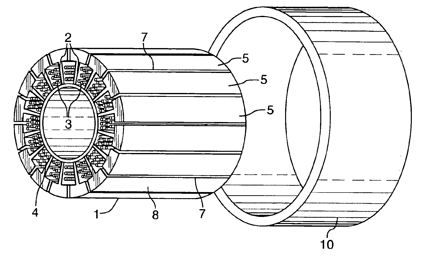
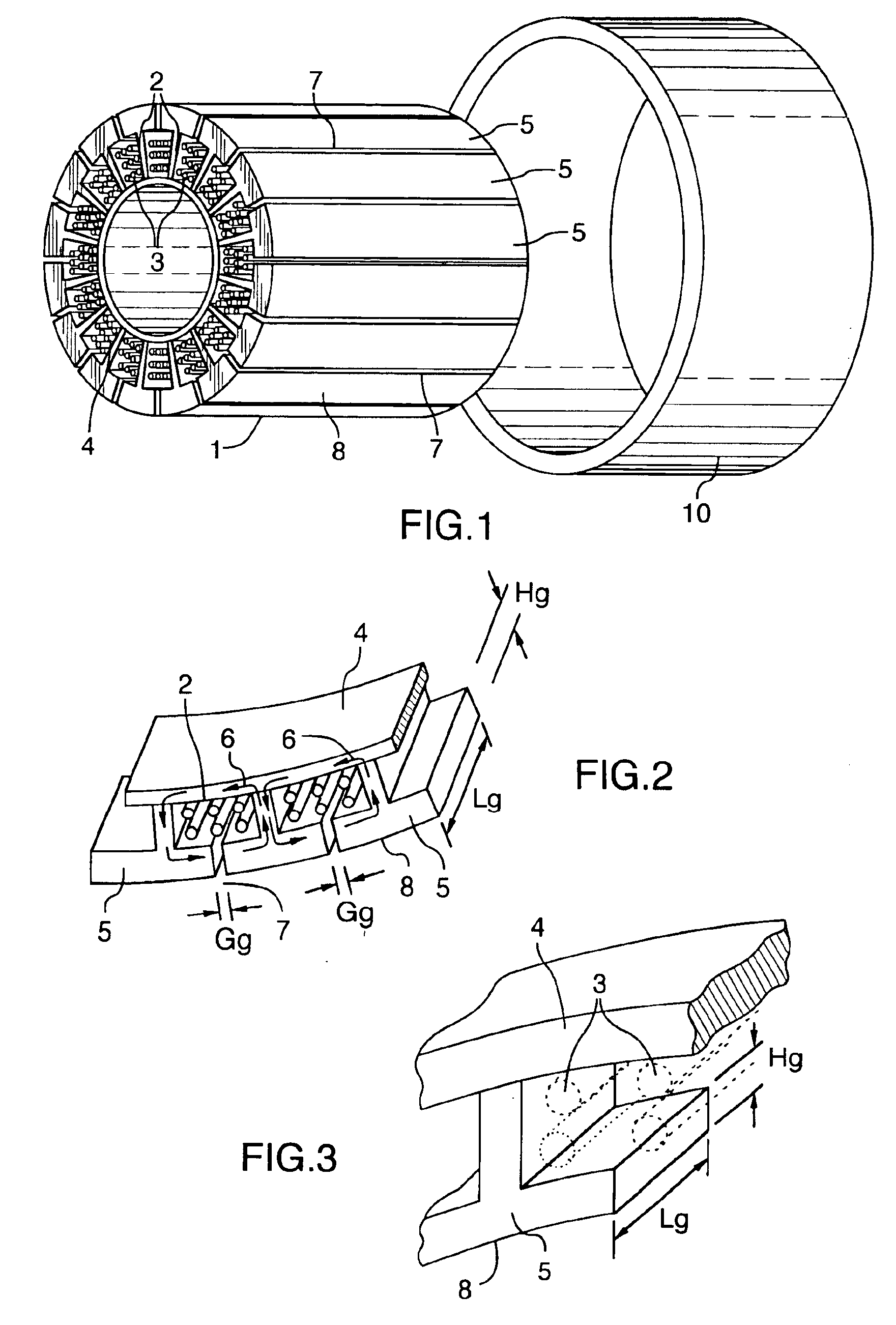
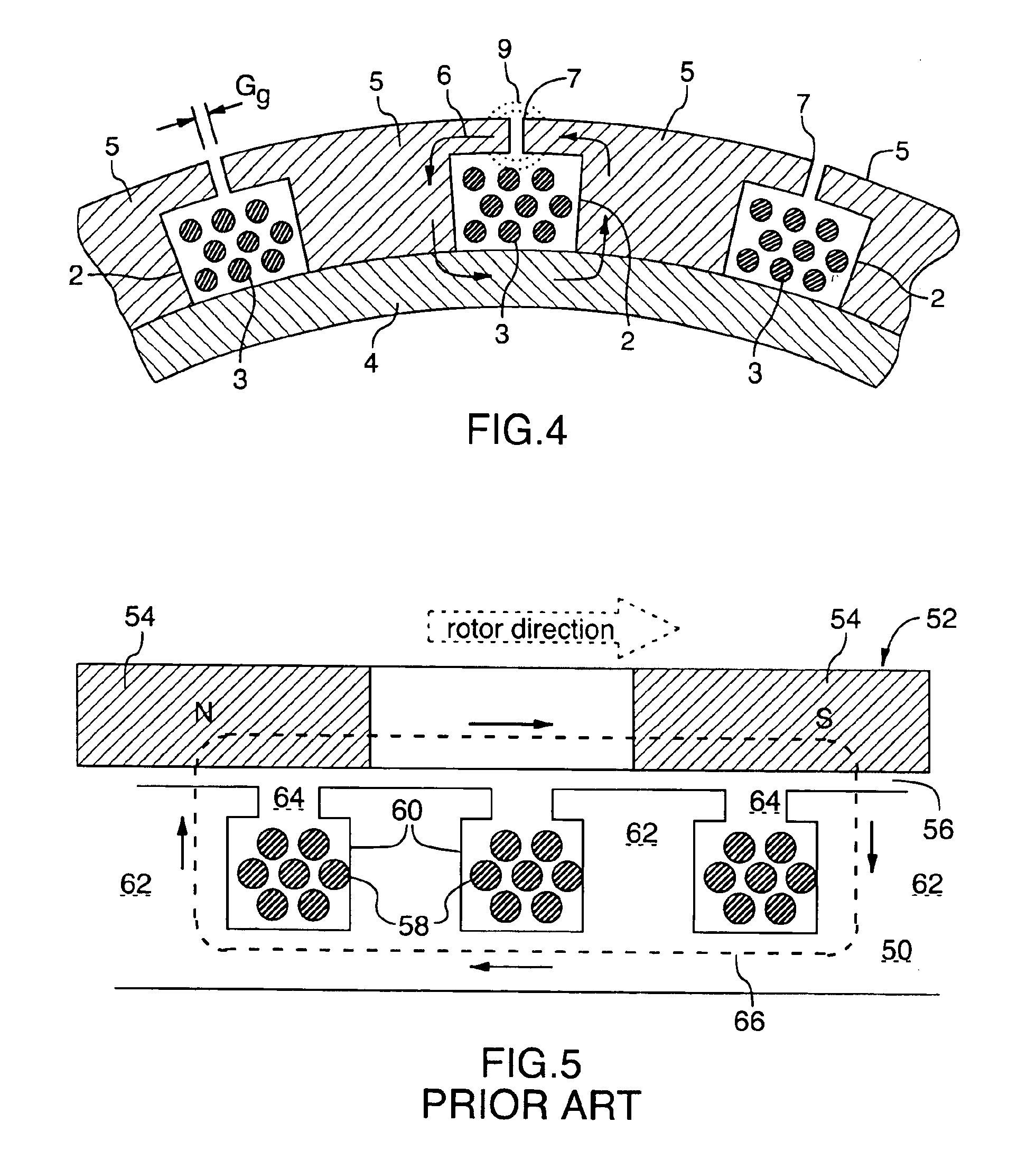
[0050]In the prior art, the designer focused on manufacturing considerations in selecting an electric machine's winding gap sizes, in an effort to ensure that the selecting conductor sizes permitted the desired number of turns to be efficiently provided in the stator slots using automatic winding machines. Other manufacturing considerations also preoccupied the designer in selecting the winding gap size. In contrast, the present invention frees the designer from such considerations by providing alternate means to provide the winding in the slot, and therefore, the slot gap 7 on face 8 adjacent the rotor is available for application of the short circuit limiting concept of the present invention.

[0051]As discussed briefly above, in prior art electric machines (see FIG. 5), the size of the conductor windings 3 and other assembly parameters typically define the width Gg of the gap 7. However, by the provision of a multi-piece stator 1, thereby eliminating the need to insert the windings...


PUM


Abstract

The invention provides means of limiting maximum current conducted through windings of an electric machine having a rotor and a stator. By encouraging an appropriate leakage flux around a winding, a leak impedance can be achieved which may be used, according to the invention, to limit the maximum current in the winding as a matter of machine design.

Description

TECHNICAL FIELD[0001]The invention relates to means of limiting the maximum current, including a short circuit current, in windings of an electric machine such as a generator or motor.BACKGROUND OF THE ART[0002]The need for preventing short circuit overloading of circuits in electric generators and motors is well recognized. Protective external circuits and equipment are often provided with fusible materials or electronic controls external to the windings of the electric machine, however internal short circuit conditions may occur within the windings of a motor / generator that would not be detected or controlled by external fusing or controls.[0003]One approach to providing protection within the windings is disclosed in the inventor's U.S. Pat. No. 6,313,560. Due to the heat generated by high currents and high rotational speeds of machines used in “more electric” aircraft engines, the electric motor / generator and the insulated wiring conductors must be sufficiently protected from the...

Claims


Application Information

Patent Timeline
Patent Type & Authority Patents(United States)
IPC IPC(8): H02K1/16H02K11/00
CPCH02K1/165H02K11/00
Inventor DOOLEY, KEVIN ALLAN
Owner PRATT & WHITNEY CANADA CORP
Why Eureka
Try Eureka