Thin-type surface-mount capacitor

a surface-mount capacitor, thin-type technology, applied in the direction of electrolytic capacitors, capacitor electrodes, liquid electrolytic capacitors, etc., can solve the problems of insufficient preventive measures against oxygen invasion, difficult to increase the adhesion between anode terminals and casing resins, and the structure of capacitors also has drawbacks. , to achieve the effect of excellent high-temperature durability

Inactive Publication Date: 2005-07-19
TOKIN CORP +1
View PDF7 Cites 6 Cited by
  • Summary
  • Abstract
  • Description
  • Claims
  • Application Information

AI Technical Summary

Benefits of technology

[0009]It is therefore an object of this invention to provide a non-cased thin-type surface-mount capacitor that can inhibit invasion of oxygen into the inside of the capacitor, and that is reliable and excellent in high-temperature durability.

Problems solved by technology

However, by means of the molding, it is difficult to increase adhesion between an anode terminal and the casing resin for tightly sealing therebetween.
Therefore, the preventive measure against the invasion of oxygen is not sufficient.
Further, the structure of this capacitor also has a drawback that the size increases.
However, this causes an increase in production cost.
Therefore, the thermal adhesive resin impregnated tape does not fully cover the cathode layer including the conductive functional polymer film, and thus there are exposed portions to easily allow invasion of oxygen.
Accordingly, like the prior art 1, the prior art 2 also has a drawback that the electrolyte layer in the form of the conductive functional polymer film is liable to be oxidized.

Method used


Image

  • Thin-type surface-mount capacitor
  • Thin-type surface-mount capacitor
  • Thin-type surface-mount capacitor

Examples


Embodiment Construction

[0017]For facilitating better understanding of this invention, the conventional surface-mount type capacitors will first be described with reference to FIGS. 1 and 2.

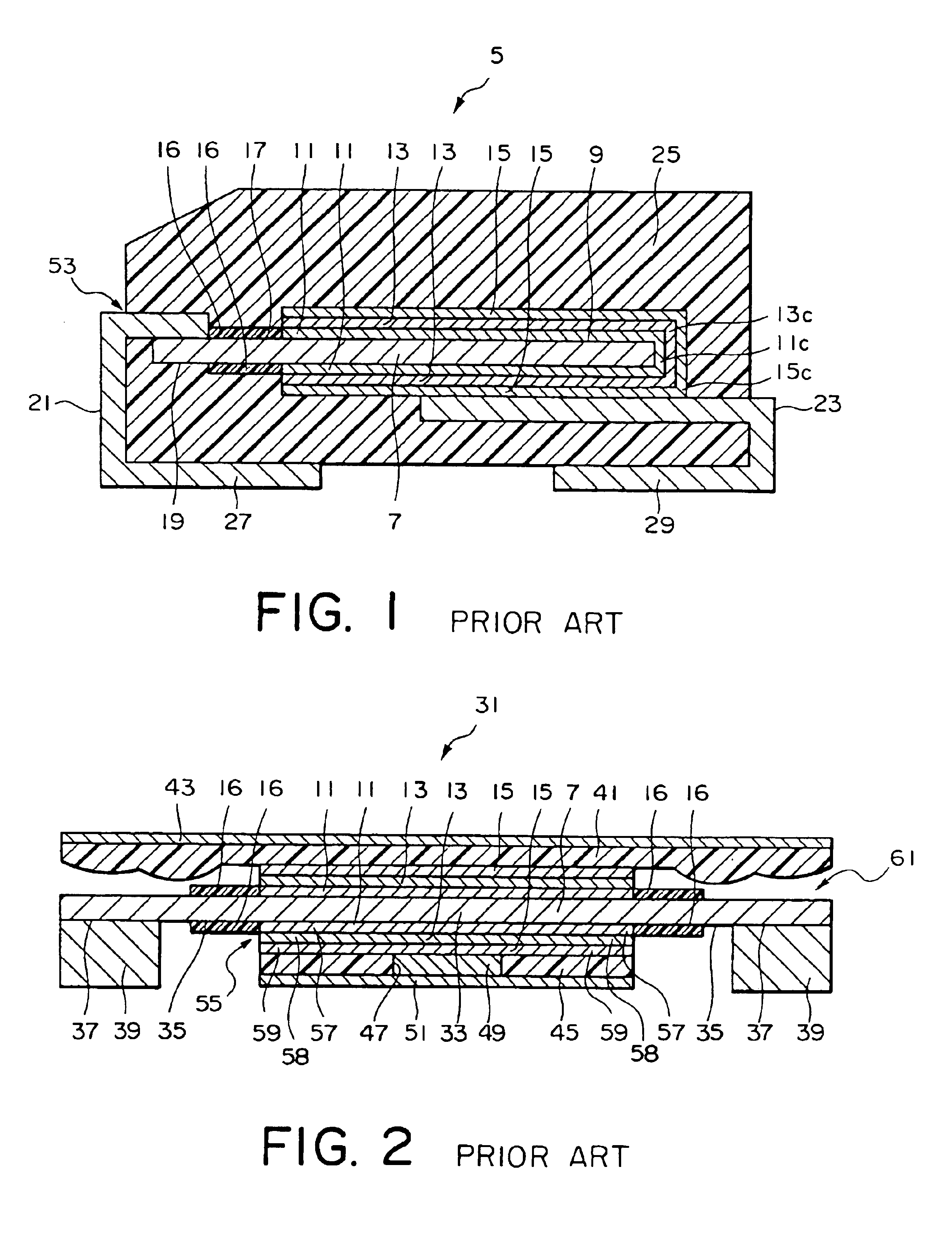
[0018]FIG. 1 shows a solid electrolytic capacitor 5 according to the prior art 1. The illustrated capacitor 5 is called the two-terminal mold type. In the capacitor 5, a conductive functional polymer film 11 is used as a solid electrolyte, and a valve-action metal anode body 7 comprises a foil of aluminum being a valve-action metal and an anode oxide film formed on the aluminum foil.

[0019]On the anode oxide film, the conductive functional polymer film 11 is formed at a portion 9 of the anode body 7 so as to cover one end thereof. Further, a graphite layer 13 is formed around the conductive functional polymer film 11, and a conductive layer 15 in the form of a silver paste layer is formed around the graphite layer 13. Then, at the other end 19 of the anode body 7 on an upper side thereof, a lead 21 is connected so as to ...


PUM

PropertyMeasurementUnit
lengthaaaaaaaaaa
conductiveaaaaaaaaaa
thermal adhesiveaaaaaaaaaa

Abstract

A thin-type surface-mount capacitor is a solid electrolytic capacitor. The capacitor includes a capacitor element having an anode body in the form of a plate-like or foil-like valve-action metal that is area-increased, and a conductive functional polymer film used as a solid electrolyte. The capacitor further includes thermal adhesive insulating resin impregnated tapes that are stuck to the capacitor element on upper and lower sides thereof, and an element reinforcing metal plate and a solderable cathode terminal metal plate 67 that are stuck to the tapes, respectively. The capacitor is finally formed by applying a curing treatment under high temperature and pressure. Each of the metal plates is applied with a stepping process that provides a difference in level corresponding to a predetermined thickness.

Description

[0001]This application claims priority to Japanese Patent Application JP 2003-274156, the disclosure of which is incorporated herein by reference.BACKGROUND OF THE INVENTION[0002]This invention relates to a solid electrolytic capacitor using a polymer as an electrolyte and, more specifically, relates to a thin-type surface-mount capacitor.[0003]As capacitors of this type, there have been known those capacitors described in, for example, Japanese Patent Application Publication (JP-A) H05-275290 (hereinafter, the capacitor described in this publication will be referred to as the solid electrolytic capacitor according to the prior art 1) and Japanese Patent Application Publication (JP-A) 2002-313676 (hereinafter, the capacitor described in this publication will be referred to as the solid electrolytic capacitor according to the prior art 2).[0004]The solid electrolytic capacitor according to the prior art 1 is called the two-terminal mold type. In this capacitor, a conductive functiona...

Claims


Application Information

Patent Timeline
Patent Type & Authority Patents(United States)
IPC IPC(8): H01G9/00H01G9/012H01G9/15
CPCH01G9/15H01G11/56Y10T29/417Y02E60/13
Inventor NAGASAWA, TOSHIHISAKAWAI, AKIHIROMARUKO, YUICHI
Owner TOKIN CORP
Why Eureka
Try Eureka