Self-sustaining control for a heating system

a self-sustaining control and heating system technology, applied in the field of heating systems, can solve the problems of reducing system efficiency and lack of energy source for ignition of pilot burners in the heating system, and achieve the effect of improving the overall efficiency of the heating system

Active Publication Date: 2005-07-19
ADEMCO INC
View PDF7 Cites 34 Cited by
  • Summary
  • Abstract
  • Description
  • Claims
  • Application Information

AI Technical Summary

Benefits of technology

[0005]The control includes a controller, directing the operational mode of the heating system in accordance with a need-based protocol, a storage device and a thermo-electric assembly. In the absence of a heating demand, the controller places the heating in the “OFF” mode. In response to a heating demand, the controller interconnects the pilot burner assembly and storage device to initiate the PILOT-ON mode, and the storage device powers ignition of the pilot burner assembly. The thermo-electric assembly responsively provides a potential that powers the heating system and controller during operation in the PILOT-ON and ON modes.
[0007]It is thus an object of the present invention to provide an efficient, self-sustaining heating system. Another object is gas-powered heating system with a self-sustaining control. Still another object of the present invention is a self-sustaining control for a heating system, whereby the overall efficiency of the heating system is improved. It is yet another object to provide a heating system, powered by a storage device, wherein operation is ensured regardless of the temporary expiration of the storage device.

Problems solved by technology

For areas where electricity is unavailable, the heating system lacks an energy source for ignition of the pilot burner assembly whenever there is a demand for heating.
That is, once the pilot burner assembly is manually lit as a part of the start-up procedure, the pilot burner assembly burns continuously, significantly diminishing system efficiency.

Method used


Image

  • Self-sustaining control for a heating system
  • Self-sustaining control for a heating system

Examples


Embodiment Construction

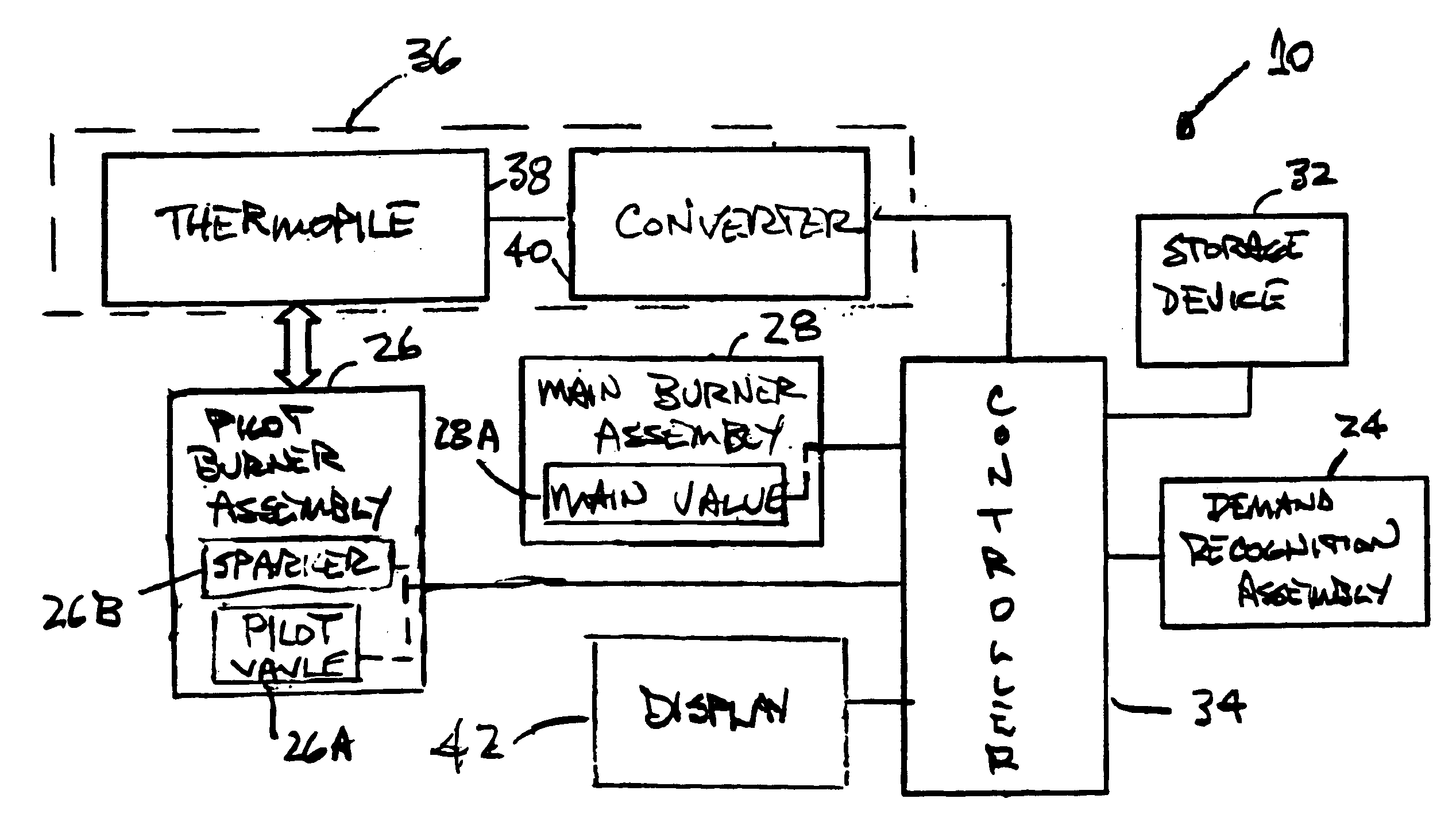
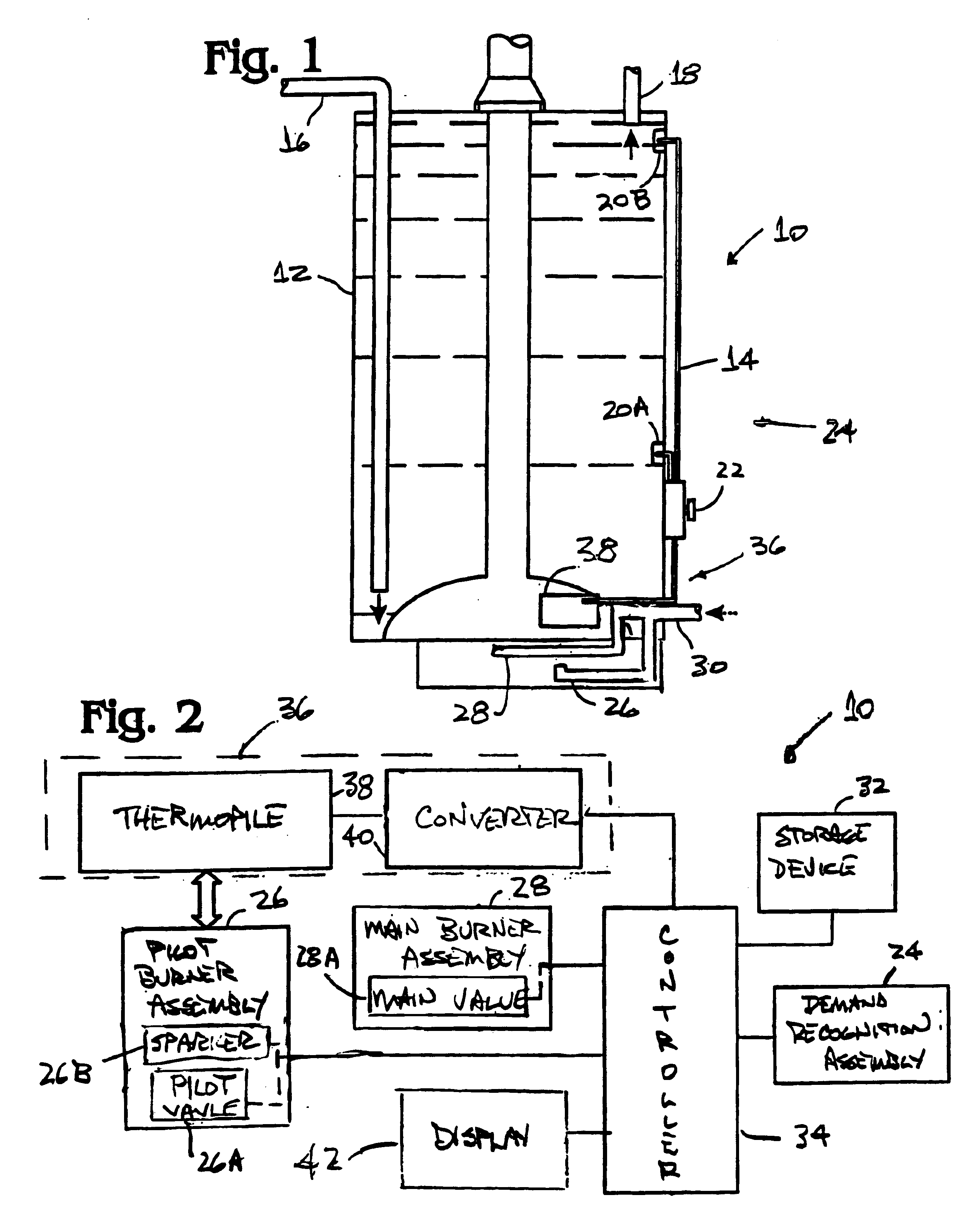
[0012]A first preferred embodiment of the present invention is shown in FIGS. 1 and 2 as a self-sustaining control, generally designated 10, for a gas-powered water heater 12. It is to be understood, however, that the control 10 is equally adaptable to other heating systems, such as a furnace or fireplace insert. (As used herein, the term “heating system” includes all such heating systems.)

[0013]The water heater 12 is conventional and includes a tank 14, water inlet 16 and outlet 18. Conventional sensors 20A, 20B and adjustable temperature selector 22 monitor water temperature in the tank 14 and cooperate in a conventional manner to define a demand recognition assembly 24 for providing a demand signal whenever that temperature falls below the set point, established by the selector 22. The water heater 12 further includes a pilot burner assembly 26, having a pilot valve 26A and a sparker 26B, and a main burner assembly 28, having main valve 28A. The valves 26A, 28A provide convention...


PUM


Abstract

A self-sustaining control for a heating system, having conventional operational modes and pilot burner assembly, is disclosed. A controller directs operation in accordance with a need-based protocol and monitors the condition of a storage device, which provides system power during the stand-by or off mode under normal conditions. A thermo-electric device is in thermal communication with the pilot burner assembly and powers the system whenever the pilot is lit. Regardless of heat need, the controller directs operation in a pilot-on mode, in lieu of an off mode, whenever the storage device is compromised.

Description

BACKGROUND OF THE INVENTION[0001]The present invention relates generally to a heating system and, more particularly, to a control, powered by a storage device and a thermoelectric assembly, to ensure operation of the heating system whenever the storage device is compromised, i.e., a self-sustaining control, and to enhance efficiency.[0002]Gas-powered heating systems are well known. (As used herein, the term “gas-powered” refers to use of natural gas, propane or any other fossil fuel as the fuel source.) Such heating systems are operable in three conventional modes—the stand-by or “OFF” mode, the heating or “ON” mode and the intermediate or “PILOT-ON” mode.[0003]For areas where electricity is unavailable, the heating system lacks an energy source for ignition of the pilot burner assembly whenever there is a demand for heating. As such, the heating system is designed to operate in the “PILOT-ON” mode in the absence of a heating demand and in the “ON” mode in the presence of a heating ...

Claims


Application Information

Patent Timeline
Patent Type & Authority Patents(United States)
IPC IPC(8): F24H9/20G05D23/19F24D18/00
CPCF24H9/2035G05D23/1909F24H2240/08F24D18/00F24D2101/60F24H2240/01F24H15/223F24H15/395F24H15/36F24H15/414F24H15/31
Inventor CHIAN, BRENT
Owner ADEMCO INC
Why Eureka
Try Eureka