Hollow plastic section

a technology of hollow plastic and hollow section, applied in the field of hollow plastic section, can solve the problems of insufficient adhesion through gluing or forced connection, insufficient heat insulation, and insufficient heat insulation, and achieve the effect of small volume and small cross section

Inactive Publication Date: 2005-07-26
SCHUCO INT KG
View PDF27 Cites 19 Cited by
  • Summary
  • Abstract
  • Description
  • Claims
  • Application Information

AI Technical Summary

Benefits of technology

[0011]The plurality of inner chambers, which have a small cross section and small volume only, prevents the formation of a convection flow which would impair the heat insulation.
[0012]The stiffening elem

Problems solved by technology

This adhesion through gluing or forced connection is insufficient in conjunction with the force transfer through dynamic loads upon the hollow plastic section in order to ensure the shearing strength between the reinforcement band and the frame section.
Furthermore, the known frame profile has an interior ch

Method used


Image

  • Hollow plastic section
  • Hollow plastic section
  • Hollow plastic section

Examples


Embodiment Construction

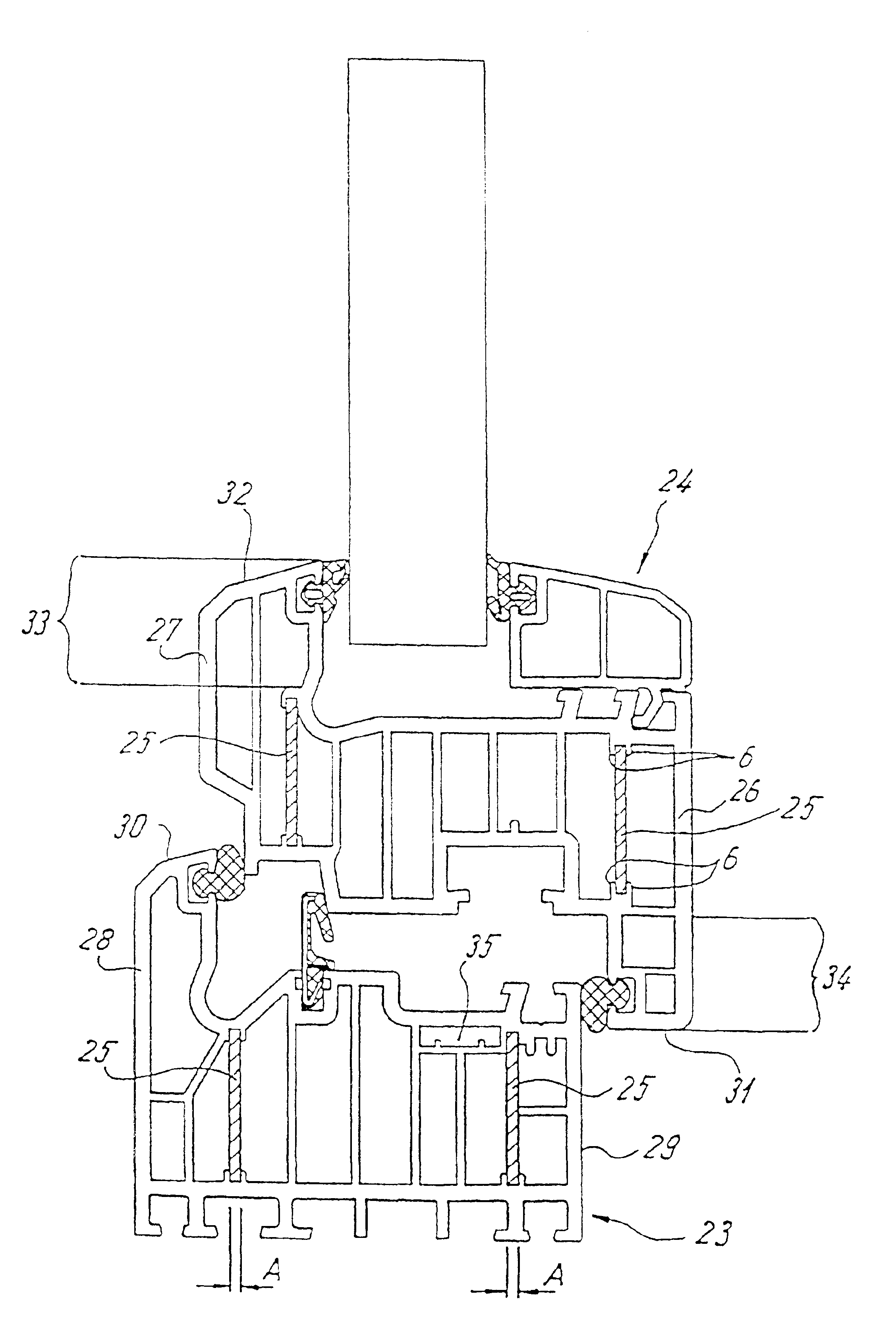
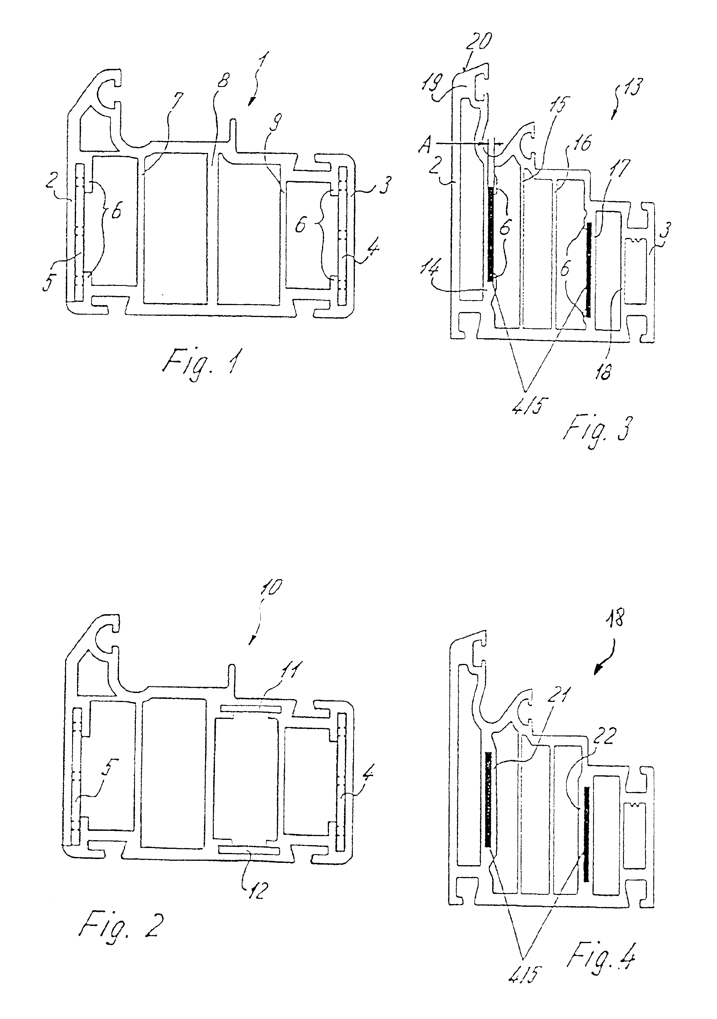
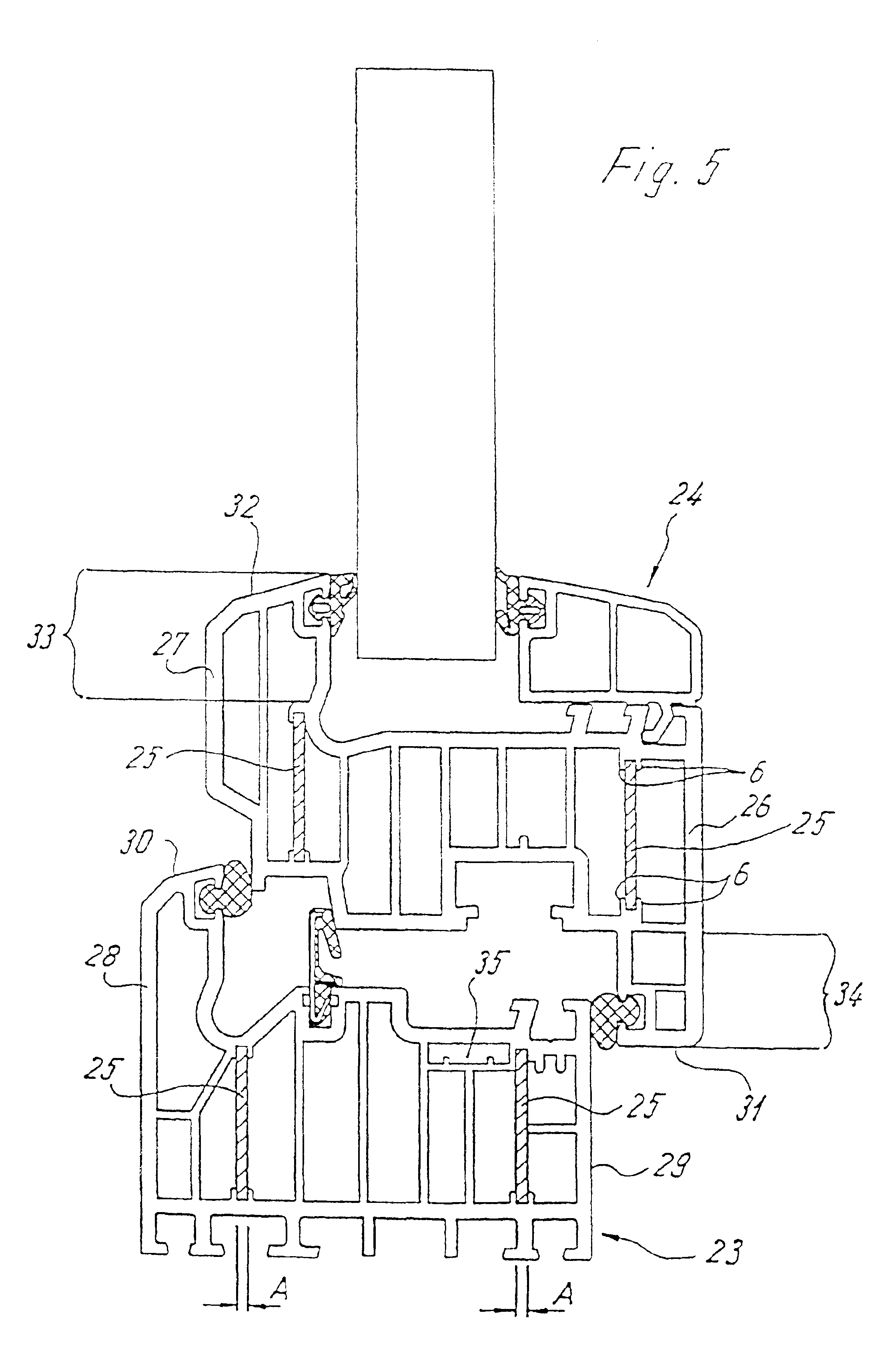
[0022]Throughout all the Figures, same or corresponding elements are generally indicated by same reference numerals.

[0023]Turning now to the drawing, and in particular to FIG. 1, there is shown a sectional view of a frame section, generally designated by reference numeral 1 and useable for windows and doors. The frame section 1 is made of plastic and has band-shaped or strip-shaped stiffening elements 4, 5 made of metal or fiber-reinforced plastic and disposed on the inner sides of exterior walls 2, 3. The exterior walls 2, 3 form the visible surfaces of the frame section 1 and have a dimension which is only slightly impacted by the arrangement of the strip-shaped stiffening elements 4, 5. The stiffening elements 4, 5 are located in semi-open or closed chambers and are secured there resistant to shearing through adhesion or through positive fit.

[0024]Normally, the stiffening elements are co-extruded during fabrication of the frame section 1.

[0025]In the exemplified embodiment of the...


PUM

PropertyMeasurementUnit
Structureaaaaaaaaaa
Areaaaaaaaaaaa
Distanceaaaaaaaaaa

Abstract

A hollow plastic section, includes a frame section defining a longitudinal axis and having an interior subdivided in several inner chambers by a plurality of partition walls extending in a direction of the longitudinal axis, Received in the interior is a plurality of stiffening elements arranged separate from one another, without interconnection, for realizing a reinforcement of the frame section. The stiffening elements may be made of metal or may be configured as bands or strips of fiber-reinforced plastic.

Description

CROSS-REFERENCES TO RELATED APPLICATIONS[0001]This application is a continuation of prior filed copending PCT International application no. PCT / EP00 / 06636, filed Jul. 12, 2000.[0002]This application claims the priority of German Patent Applications, Serial No. 199 33 099.9, filed Jul. 15, 1999, and 299 12 375.8, filed Jul. 15, 1999, the subject matter of which is incorporated herein by reference.BACKGROUND OF THE INVENTION[0003]The present invention relates to a hollow plastic section with embedded metallic reinforcement, and more particularly to a frame section for windows or doors.[0004]German utility model DE-GM 81 11 425 describes a plastic frame section in which the fiber-reinforced plastic bands are either embedded in the outer walls or secured to the inner side of the outer wall by a foamed core or by glue. Attachment of these fiber-reinforced plastic bands is realized solely by the adhesion between the individual materials. This adhesion is effected by an adhesive action of ...

Claims


Application Information

Patent Timeline
IPC IPC(8): E06B3/22E06B3/04E06B3/263B32B3/10E06B3/26E06B7/14E06B7/23
CPCE06B3/221E06B3/222E06B7/14E06B7/2305E06B2003/224E06B2003/225E06B2003/228E06B2003/26323E06B2003/26327Y10S49/02
Inventor BIELEFELD, HANS-WALTERSENNECA, MATTHIASKAMPER, RALF
Owner SCHUCO INT KG
Why Eureka
Try Eureka