Exhaust emission control device of internal-combustion engine

a technology of exhaust emission control and combustion engine, which is applied in the direction of electric control, machines/engines, mechanical equipment, etc., can solve the problems of nosub>x /sub>spike, nox is not satisfactorily converted, and osub>2 /sub>storage components are easily saturated, so as to prevent nox spike in rich air-fuel ratio operation and maintain high efficiency in converting nox

Inactive Publication Date: 2005-07-26
MITSUBISHI MOTORS CORP
View PDF7 Cites 0 Cited by
  • Summary
  • Abstract
  • Description
  • Claims
  • Application Information

AI Technical Summary

Benefits of technology

[0013]The invention has been made to solve the above problems. An object of the invention is to provide an exhaust emission control device of an internal-comb...

Problems solved by technology

Hence, even the three-way catalyst having an OSC has a problem that HC is not converted satisfactorily in rich air-fuel ratio operation (see FIG.
However, while a fuel cut is performed, O2 is discharged as it is, so that the O2 ...

Method used


Image

  • Exhaust emission control device of internal-combustion engine
  • Exhaust emission control device of internal-combustion engine
  • Exhaust emission control device of internal-combustion engine

Examples


Embodiment Construction

[0024]An embodiment of the invention will be described on the basis of the drawings.

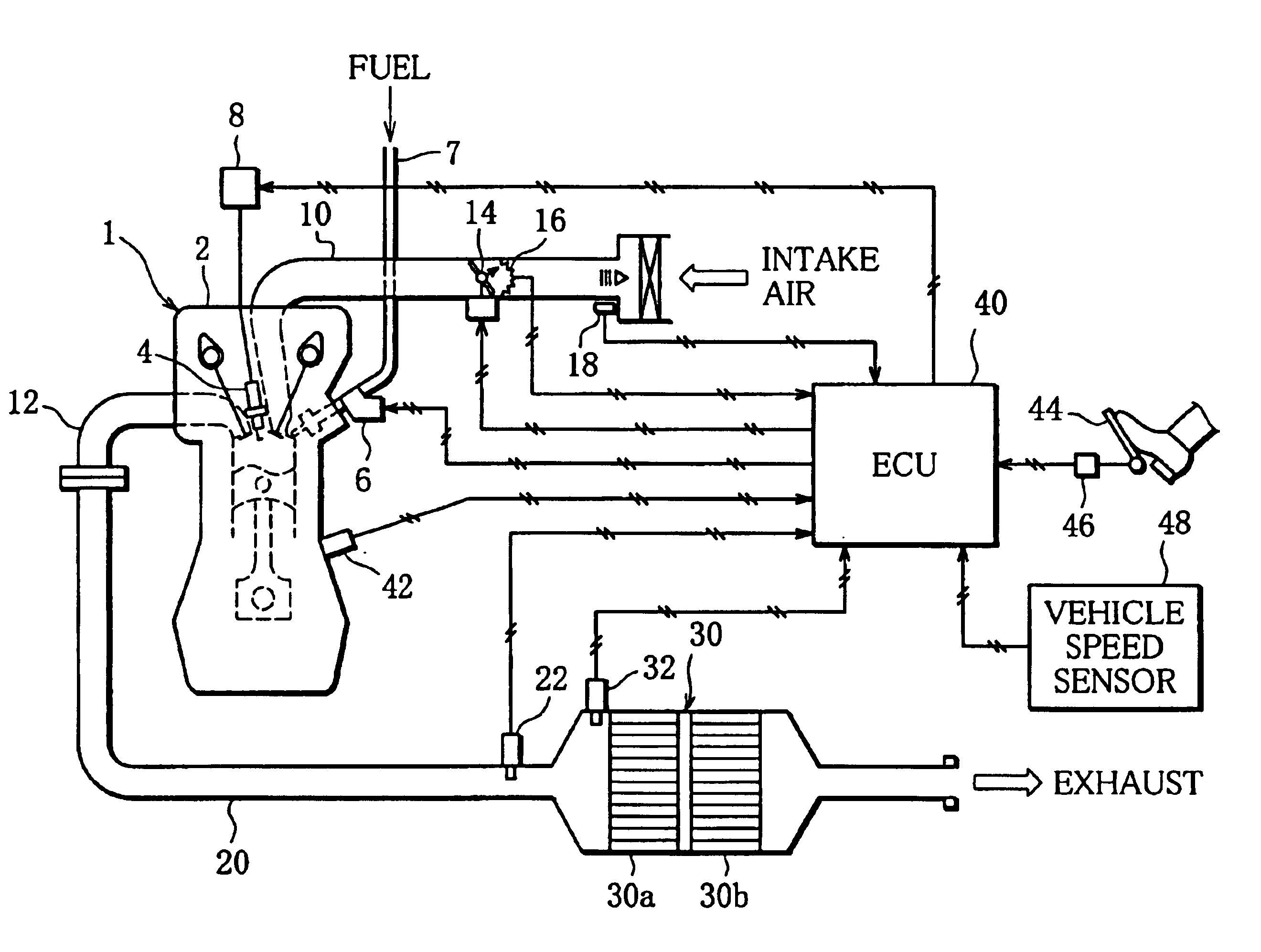
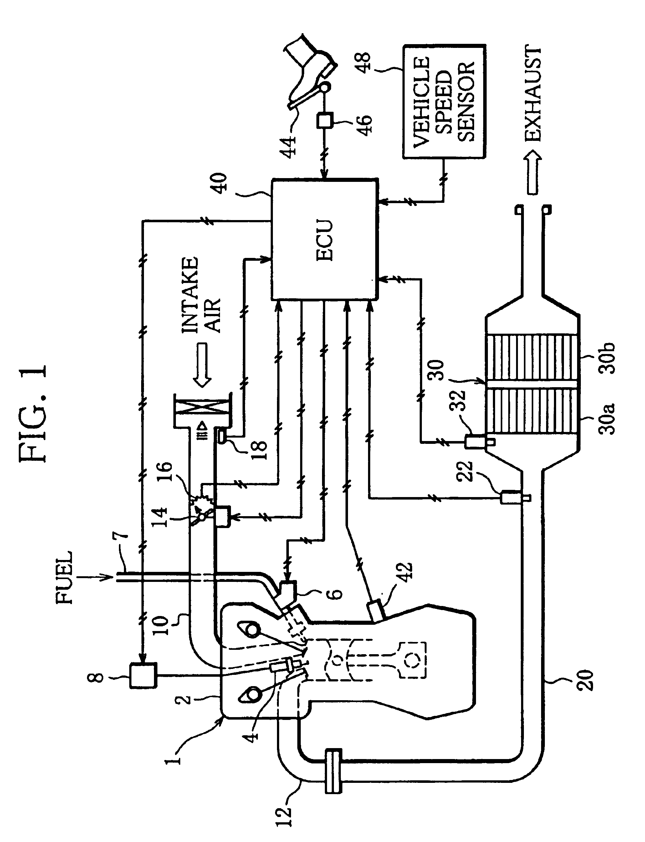
[0025]FIG. 1 schematically shows structure of an exhaust emission control device of an internal-combustion engine according to the invention, mounted on a vehicle. On the basis of FIG. 1, the structure of the exhaust emission control device according to the invention will be described below.

[0026]As shown in FIG. 1, as a basic engine (hereinafter referred to simply as “engine”) 1, for example, a cylinder-injection spark-ignition gasoline engine which can perform fuel injection in an intake stroke (intake-stroke injection) or fuel injection in a compression stroke (compression-stroke injection) in accordance with a selected fuel injection mode is adopted. The cylinder-injection engine 1 can easily operate at a lean air-fuel ratio (lean air-fuel ratio operation) in addition to a stoichiometric air-fuel ratio (stoichiometric air-fuel ratio operation) and a rich air-fuel ratio (rich air-fuel ratio operat...


PUM


Abstract

An exhaust emission control device of an internal-combustion engine comprises a three-way catalytic converter provided in an exhaust passage of the internal-combustion engine, and an air-fuel ratio varying element for forcedly varying an air-fuel ratio of exhaust flowing into the three-way catalytic converter, between a rich air-fuel ratio and a lean air-fuel ratio. A variation characteristic altering element for altering a characteristic of the air-fuel ratio variation is provided, and the three-way catalytic converter has a HC selective oxidizing component for selectively oxidizing HC rather than CO, and a CO storage component for storing CO in a reducing atmosphere. The variation characteristic altering element alters a characteristic of the air-fuel variation (such as an A/F variation period) depending on an stored CO quantity correlative value (such as a quantity of flowing-in CO) which correlates with a quantity of CO stored by the CO storage component (S12).

Description

CROSS-REFERENCE TO THE RELATED ART[0001]This application incorporates by reference the subject matter of Application No. 2002-260364, field in Japan on Sep. 5, 2002, on which a priority claim is based under 35 U.S.C § 119(a).BACKGROUND OF THE INVENTION[0002]1. Field of the Invention[0003]The invention relates to an exhaust emission control device of an internal-combustion engine, specifically to a technique of increasing efficiency in converting exhaust emissions using a three-way catalyst.[0004]2. Description of the Related Art[0005]As a catalyst for exhaust emission control of an internal-combustion engine for a vehicle, a three-way catalyst is generally used broadly.[0006]Recently, in order to make full use of the capabilities of a three-way catalyst, a three-way catalyst having a so-called O2 storage component (hereinafter abbreviated to “OSC”) has been developed. In lean air-fuel ratio operation of an internal-combustion engine, the three-way catalyst having the OSC stores O2, ...

Claims


Application Information

Patent Timeline
IPC IPC(8): F02D41/14F01N3/08F01N3/10F01N3/28F02D41/04
CPCF01N3/0857F02D41/1475F01N2430/06F01N2570/12F02D41/1441Y02T10/20Y02T10/22Y02T10/12F01N3/10
Inventor TAMURA, YASUKI
Owner MITSUBISHI MOTORS CORP
Why Eureka
Try Eureka