Gas turbine and the combustor thereof

a technology of gas turbine and combustor, which is applied in the direction of machines/engines, mechanical equipment, lighting and heating apparatus, etc., can solve the problems of easy blowout of flame, limited stable operation, and easy combustion oscillation, and achieve the effect of suppressing the fluctuation

Inactive Publication Date: 2005-07-26
MITSUBISHI HEAVY IND LTD
View PDF5 Cites 21 Cited by
  • Summary
  • Abstract
  • Description
  • Claims
  • Application Information

AI Technical Summary

Benefits of technology

[0025]It is thought that said fluctuation in heat liberation is due to the fluctuation in the state of mixing of fuel and air at the premixing nozzles and this fluctuation is propagated through the premixing nozzles to the upstream side. The combustion oscillation of super high frequency is a plane vibration having nodes on the planes orthogonal to the axis of the flame tube, i.e. plane mode vibration as shown in FIG. 3, so interaction between the nozzles occurs also in the upstream side of the premixing nozzles. By preventing or restricting the propagation of the sound pressure of this part by partition plates such as plates with many holes or pressure shield plates, the suppression of the propagation of sound pressure in the direction along a section transversal to the axis of the combustor (cluster of premixing nozzles) in the circumferential direction around the axis thereof is possible and the super high frequency combustion oscillation can be suppressed.
[0028]Further, by forming the premixing nozzles of porous material so as to suppress the fluctuation in the state of fuel / air mixing at the premixing nozzles, the propagation of sound pressure in the direction along a section transversal to the axis of the combustor (cluster of premixing nozzles) in the circumferential direction around the axis thereof be further more suppressed, resulting in the suppression of the super high frequency oscillation of combustion.

Problems solved by technology

However, in lean premixed combustion, generally a flame blowout is easy to occur as compared with diffusive combustion in which fuel burns while mixing with air, and also combustion oscillation is easy to occur.
In addition, the stable operation is limited.
However, with the prior art described above, combustion oscillation of very high frequency (super high-frequency combustion oscillation) which forms the acoustic mode (sound pressure mode) in the plane transversal to axis of the combustor occurs due to the coupling of the acoustic system and combustion system.
However, as the cylindrical element with many holes 10 is located in the high temperature zone of combustion, design consideration of heat resistance and cooling of the cylinder is inevitable, which results in a complicated structure and increased manufacturing costs.

Method used


Image

  • Gas turbine and the combustor thereof
  • Gas turbine and the combustor thereof
  • Gas turbine and the combustor thereof

Examples


Embodiment Construction

[0036]A preferred embodiment of the present invention will now be detailed with reference to the accompanying drawings. It is intended, however, that unless particularly specified, dimensions, materials, relative positions and so forth of the constituent parts in the embodiments shall be interpreted as illustrative only not as limitative of the scope of the present invention.

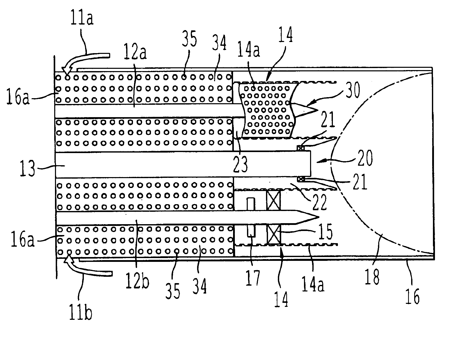
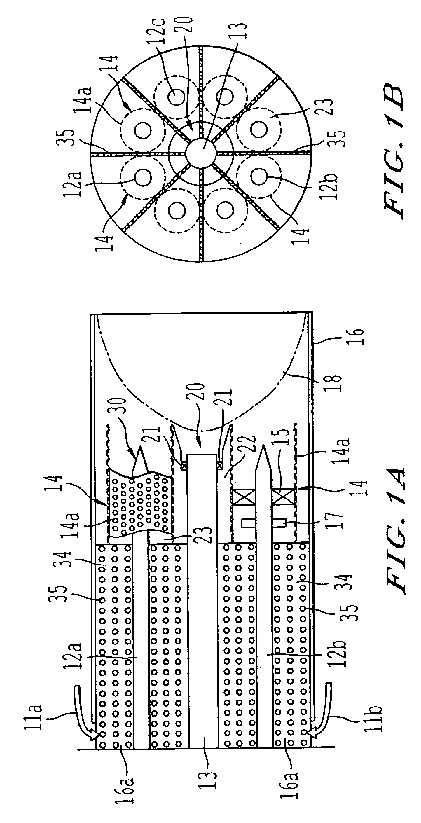
[0037]FIGS. 1(A), (B) are schematic illustrations of a combustor in which diffusion combustion is combined with premixed combustion, FIG. 1(A) is a longitudinal sectional view showing the inner structure of the combustor of first embodiment according to the present invention, and FIG. 1(B) is a cross sectional view thereof.

[0038]In the drawings, the combustor is composed of a pilot burner 20 for diffusive combustion provided on the center axis of a substantially cylindrical flame tube (liner) 16, the pilot burner 20 being provided with a pilot fuel supply nozzle 13 having a pilot swirler vane 21 attached around ...


PUM


Abstract

The objective is to provide a gas turbine and the combustor thereof in which super high frequency combustion oscillation and the generation of NOx are reduced.The fluctuation in pressure which induces the fluctuation in heat liberation is suppressed in the gas turbine combustor comprising a plurality of main fuel supply nozzles, each having a premixing nozzle at the top end part thereof, by providing in the space upstream from the premixing nozzles partition elements for dividing the space along the axis of the combustor or a honeycomb element having air passages in the axial direction, or by providing premixing nozzles composed of cylindrical elements with many holes.

Description

BACKGROUND OF THE INVENTION[0001]1. Field of the Invention[0002]The present invention relates to a gas turbine and the combustor thereof with reduced super high frequency oscillation of combustion and with reduced emission of NOx.[0003]2. Description of the Related Art[0004]FIG. 6 is a longitudinal sectional view near the combustor of a gas turbine equipped with a conventional combustor. The conventional combustor will be explained here with reference to the drawing. In FIG. 6, reference numeral 101 is a combustor mounted to a rotor housing 102.[0005]The combustor 101 has a fuel supply nozzle 103, a liner(flame tube) 104, and a tail tube 105. Reference numeral 106 is an outer casing. A bypass elbow 107 is attached to the tail tube 105. Reference numeral 108 is a bypass valve and 109 is an adjusting mechanism of the bypass valve 108.[0006]Reference numeral 110 is an air compressor. The compressed air 111 discharged from the compressor 110 flows inside the rotor housing 102, passes ar...

Claims


Application Information

Patent Timeline
Patent Type & Authority Patents(United States)
IPC IPC(8): F23R3/28F23R3/34F23M13/00F23M20/00
CPCF23R3/286F23M20/005F23R3/343F23R2900/00014
Inventor MATSUYAMA, KEISUKETANAKA, KATSUNORIIKEGAMI, YASUHIKOONO, MASAKIIKEDA, KAZUFUMI
Owner MITSUBISHI HEAVY IND LTD
Why Eureka
Try Eureka