Magnetic stamp printing device

a technology of magnetic stamps and positioning devices, which is applied in the direction of stamping, printing presses, printing, etc., can solve the problems of not having much artistic talent, unable to easily reposition, and seriously negating the “see-through” effect of images, etc., to achieve considerable personal or business value, high flexibility and convenience, and quick and flexible manipulation

Inactive Publication Date: 2005-07-26
BAXTER BRENT ALAN
View PDF8 Cites 20 Cited by
  • Summary
  • Abstract
  • Description
  • Claims
  • Application Information

AI Technical Summary

Benefits of technology

[0014]An important primary object of my invention therefore is to provide a highly flexible and convenient means of creating magnetically repositionable, moveable, removable, interchangeable, customizable and combinable rubber stamps. In this invention single stamps could be quickly and flexibly manipulated in virtually an infinite variety of ways, several stamps can be combined—to make scenes for instance—or users can stamp all their words at one time; the stamping results of this invention actually seem quite limitless.
[0015]Another object of this invention which would be of considerable personal or business value, and may find high applicability in large scale stamping operations, is to provide an efficient mechanism for speeding up the time necessary to produce a finished stamp allowing the user to quickly and functionally recombine or adjust an existing stamp image, or stamp many images on a single stamp at the same time, or single images, may be substituted, remain in use, or be used again and again. This would be of great value, for example in businesses, such as changing an employees name, or a sale item on their existing rubber stamps. Moreover, this invention could be used in assembly-line stamping such as of machinery or parts, where in the past many stamps were needed and with this invention, the same result could be accomplished with a fewer, or a single multi-purpose adjustable stamp, resulting in savings of both cost and time for the manufacturer.
[0016]A further highly useful object of this invention is to provide an educational, classroom instructional tool where pre-made letters, words and image stamps could be combined to help teach many subjects such as phonics, reading, story telling, math and science concepts, as well as many other educational pedagogical activities where children using interchangeable easily manipulatable stamp components would be helpful and desirable. In this manner, this invention would find effective usefulness in make the development of education both more fun and approachable to learners of any age and may have specific added applicability to bilingual second language learners, and special needs populations. It can also be used emphasize and teach the process of stamp making, itself.
[0017]Additionally, another useful object of this invention would be in clinical settings, where magnetic stamp member-dies could be created with select “story telling” images where individuals having trouble speaking, communicating, or “expressing* themselves” could do so through stamping. I see this specifically being used in counseling centers where frightened children, or troubled youths, could communicate using a less threatening manner of “stamp play”. These youngsters may be more inclined to communicate important information during these times when they wouldn't normally do so otherwise. Such youngsters may communicate readily during such a time of “fun and play”; and for most, stamps are synonymous with this.
[0018]A further important object of this invention is to provide a means of removably holding, collecting and storing a variety of individual stamp member-dies in a single location (such as on a magnetic sheet) so that they are easily accessed, can be maintained in an orderly fashion (e.g. alphabetically or thematically). This would also making it less likely they will be damaged or misplaced and would be characterized by the ease of removal of the said stamp member dies from their magnetically suspended positions.
[0019]Another object of this invention is that the user to readily create their own custom stamp images by simply cutting out the shapes of any image desired out of magnetic rubber material and simply and magnetically fastening these images anywhere to their stamp mount. This would be especially valuable for those wishing to expediently try out new designs and would be directly approachable to young or novice stamp users, where they could create their own images, using words, pre-cut shapes, by hand or by stencil, or any combination of pre-manufactured stamp member dies, and where they can foster pride in themselves and develop self esteem, as well as simply have fun.

Problems solved by technology

Rubber stamps are also highly appreciated by those with strong creative impulses, but may not have much artistic talent.
However, those wishing to utilize rubber stamps—from the individual consumer to large scale stamp users—have been restricted to using rubber stamps which only have permanent or non-adjustable images on them.
However, there are a number of disadvantages with either of these temporary bonding strategies described above when utilized in rubber stamping.
Some disadvantages when using Velcro on a clear mount includes the following: the image, while being able to be interchanged easily enough, cannot be easily repositioned.
A larger surface area of said stamp mount can be covered with its appropriate Velcro fastening component, to allow for repositioning; however, this will also seriously negated the “see-through” benefits of the image beneath it.
In addition, over time, portions, or all of any Velcro strip, by the nature of its interlocking hook and loop fastening will tend to wear out or become clogged with impurities and lose its adhesive effectiveness; Velcro also has bits which tend to break off over time (creating Velcro “crumbs” which could hinder stamping).
However, even this method tends to wear out over time as the acetate sheet begins to wear, bend and crinkle thereby losing much of its molecular bonding properties.
In addition, acetate sheeting has limitations regarding the weight of the stamp mount fastened, being much better with smaller lightweight pieces.
The examples above, while allowing for image replaceability, are somewhat restricted when it comes to stamp image repositioning and combinability.
In addition, this mechanism employs a complexity of holes, thin posts and heads combined to control these magnetically engaged stamp heads being “pushed out”.

Method used


Image

  • Magnetic stamp printing device
  • Magnetic stamp printing device
  • Magnetic stamp printing device

Examples


first embodiment

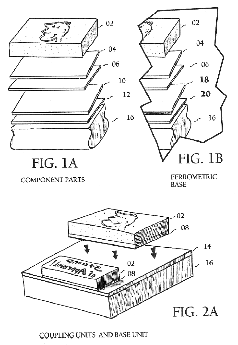
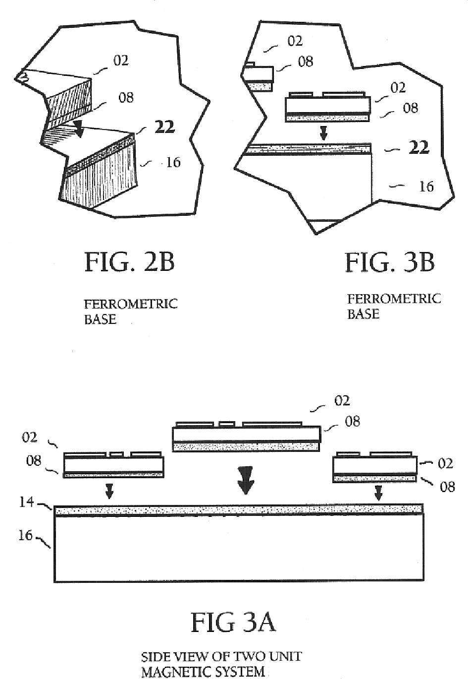
[0078]FIGS. 1A and 1B illustrate the present invention where the component parts include the following: Numeral 02 denotes the stamp member-die—any rubber-like material with a raised “mirror-image” delineation designed to hold ink from an ink pad and transfers a “corrected” ink line image onto another surface. The stamp member should have a characteristic a low rebound, low compressibility, one which will hold a high definition reproduction of the transferred image onto another surface. The stamp member-die 02 is regularly produced out of red rubber, or less expensive photopolymer; however many substances will work well and will effectively hold ink for a stamp. Even homemade cut vinyl erasers and typical rubber magnetic sheets (flexible magnetic composite materials which have magnetic particles imbedded in them). The primary removable magnetic “coupling” component of this invention is numeral 06. This is composed of a properly aligned permanent magnet or a permanently magnetized ma...

second embodiment

[0099]Referring to FIG. 4 This image details this invention. Here, FIG. 4 reveals an exploded perspective view of the magnetic stamp mount unit 14, 16; or 22,16, as it can be structurally modified to become a large surface area designed for stamp member-die storage. Here it is shown how the stamp-mount 16, is merely a flattened and enlarged version of the magnetic rubber stamp mount—now 48. Functionally, the invention remains unaltered, whereby the magnetic stamp member-die unit 02,08 can be removable attached to its companion stamp—“mount”. However, in this instance the stamp mount 16 now becomes a large magnetically attractive planar surface, a “storage area”48 for convenient and organized storage, which can hold and keep an abundant number of stamp member-dies units 02,08. (e.g. alphabetically or themed). Stamp members mounted here will be less likely to be lost or misplaced and will most certainly be easier to retrieve. Although the illustrations, for this example indicates a st...


PUM


Abstract

An improved rubber stamp fastening and printing device consisting of operatively magnetic or veritable magnetic stamp-die components and an outer magnetic connecting mount, utilizing distinct vertical magnets imbedded within a transparent material. Both the stamp-dies and mount are provided with suitable magnetic means with which to maintain a secure, yet easily manipulable magnetic bond; where these components are themselves composed of are either magnet, or ferromagnetic materials. The combination between strong slender vertical magnets or and the viewable negative spaces within the compositional translucent material create a superior transparency through the mount; this ability to directly view the see the magnetically fastened stamp-dies from reverse, allows for a very high degree of control and ability to accurately place these magnetic stamp-dies during the process of stamping. Flexible magnet or ferromagnetic sheeting can be cut by hand into various shapes and attached to the mount in order to function as alternative hand-cut magnet printing stamp-dies. Structural expansion of the stamp mount can result in a sheet storage device for holding a plurality of magnetic stamp member-dies for use in a binder system for example. The permanent magnet stamp mount of this invention, when used alone can function as a highly-translucent permanent magnet which operates in the usual magnet manner, such as a fastening magnetically reactive metal objects. Or the magnetic stamp-dies (or even the mount itself) can function by themselves as decorative and utilitarian magnets. When magnetic elements are imbedded in a non rigid transparent material, the stamp mount can be modified to create a flexible, malleable semi-transparent magnet which is capable of conforming to a high degree to the shape of the form being fastened to.

Description

CROSS-REFERENCE TO RELATED APPLICATIONS[0001]Not ApplicableSTATEMENT REGARDING FEDERALLY SPONSORED RESEARCH AND DEVELOPMENT[0002]Not ApplicableREFERENCE TO A MICROFICHE APPENDIX[0003]Not ApplicableBACKGROUND OF THE INVENTION[0004]1. Field of the Invention[0005]This invention relates to a magnetic stamp member holding and positioning device which provides a simple, economical and highly flexible means to magnetically manipulate single or multiple stamp member-dies on single stamp mount. Although the invention will find uses in other areas, its principal importance is for use in conjunction with removably, securing, combining and repositioning articles such as rubber stamp member-dies to stamping mounts, and the like, during rubber stamp printing. Both the stamp member-die and the stamp mount unit have appropriate magnetic means of the correct polarity which are aligned so as to provide a operative hold of the above mentioned components of a magnetic rubber stamp. And due to the recip...

Claims


Application Information

Patent Timeline
Patent Type & Authority Patents(United States)
IPC IPC(8): B41K1/04B41K1/00
CPCB41K1/04
Inventor BAXTER, BRENT ALAN
Owner BAXTER BRENT ALAN
Why Eureka
Try Eureka