Annular acoustic panel

a technology of annular acoustic panels and acoustic absorption, which is applied in the field of inlet absorption and attenuation of aircraft engine noise, can solve the problems of difficult to match the acoustic absorption characteristics of the acoustic treatment to the noise signature of a specific engine and associated fan assembly, and the acoustic active area of the panel is typically not available, so as to reduce the noise produced by the engine, increase the noise absorption quality

Inactive Publication Date: 2005-07-26
THE BOEING CO
View PDF17 Cites 56 Cited by
  • Summary
  • Abstract
  • Description
  • Claims
  • Application Information

AI Technical Summary

Benefits of technology

[0004]In a preferred embodiment of the present invention an aircraft engine assembly is provided that is adapted to reduce noise produced by an engine and / or fan assembly included in the engine assembly. The engine assembly includes a nacelle having an inlet section and a main section that houses the engine and fan assembly. The inlet section is coupled to the main section at a bulkhead junction between the inlet section and the main section. A one piece annular acoustic panel is located within a recess in an internal wall of the nacelle. The annular acoustic panel extends from a forward portion of the inlet section to a forward portion of the main section such that the bulkhead is covered by the annular acoustic panel. The annular acoustic panel absorbs inlet noise generated by the engine and / or fan assembly. Additionally, the annular acoustic panel can be acoustically tuned to match a noise signature of the specific engine and fan assembly, thereby increasing the noise absorption quality of the annular acoustic panel. Furthermore, the annular acoustic panel blocks the escape of noise from a forward portion of the nacelle and improves engine performance by substantially eliminating multiple leak paths within the section of the nacelle that extends forward of the fan assembly. Further yet, with respect to known acoustic treatment, the annular acoustic panel of the present invention increases the acoustic area and decreases the overall complexity.

Problems solved by technology

In such known acoustic treatment systems panel acoustically active area is typically not available around the edge bands of each individual panel or at fastener locations.
Additionally, the number of panels included in the typical acoustic treatment system makes it difficult to ‘Tune’ the acoustic treatment to best match the source noise.
That is, it is difficult to match the acoustic absorption characteristics of the acoustic treatment to the noise signature of a specific engine and associated fan assembly.
Furthermore, typical noise treatment systems have numerous leak paths that allow air, and thus noise, to escape from the engine assembly.
Further yet, in known acoustic treatment systems the high number of parts adds weight to the aircraft and increases labor and parts costs.

Method used


Image

  • Annular acoustic panel
  • Annular acoustic panel
  • Annular acoustic panel

Examples


Embodiment Construction

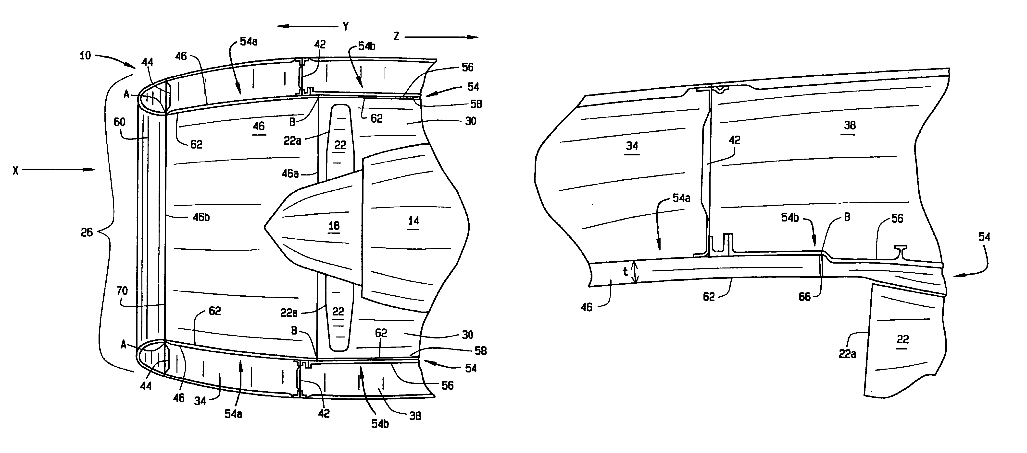
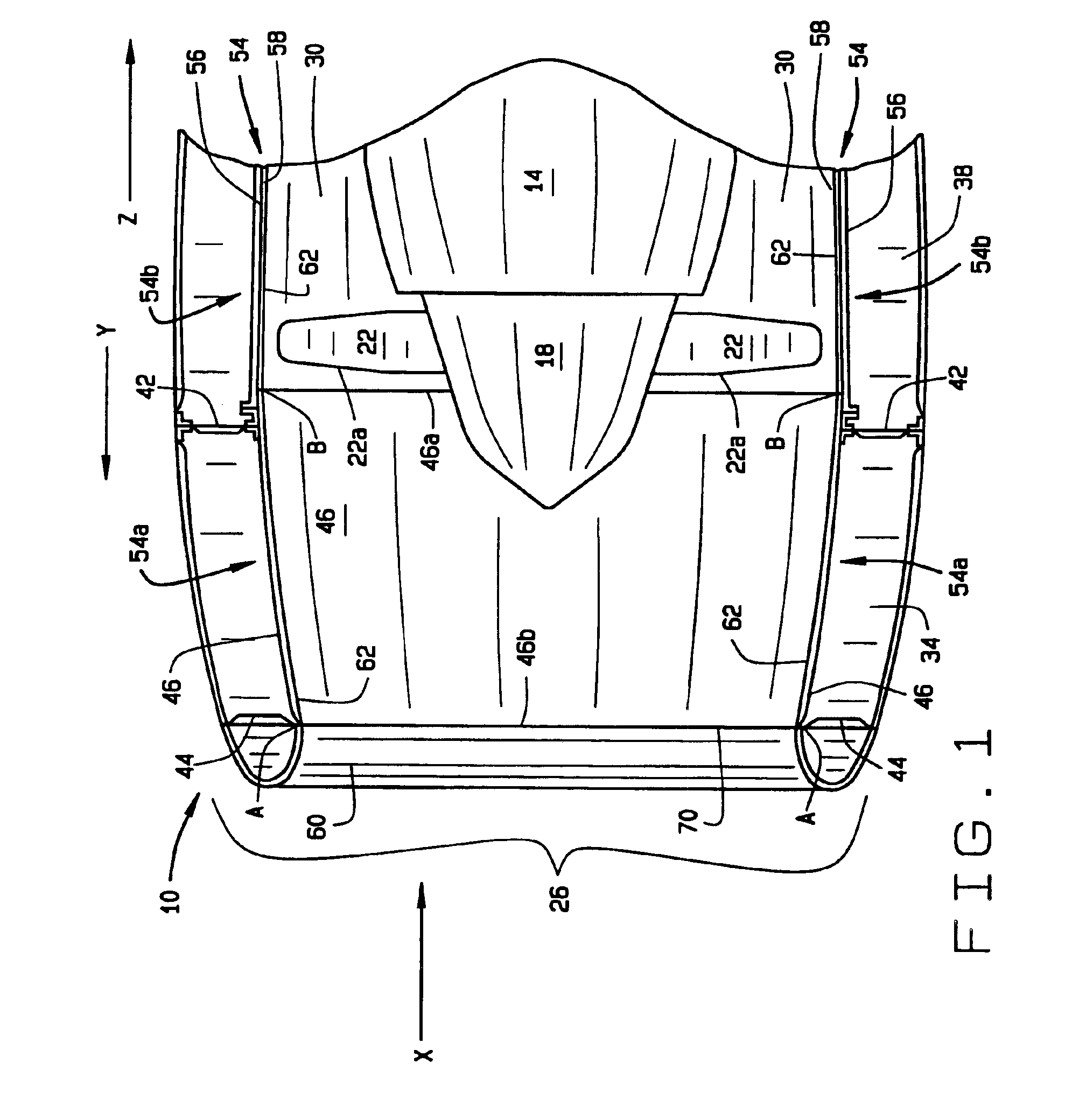
[0010]FIG. 1 is a longitudinal cross-sectional view of a portion of an aircraft engine assembly 10, in accordance with the present invention. The engine assembly includes an engine 14, for example, a gas turbine engine, and an associated fan assembly 18. The fan assembly 18 includes a plurality of circumferentially spaced fan blades 22. Surrounding the engine 14 and fan blades 22 is a nacelle 26 that is spaced radially outward from the engine 14 to define an annular duct 30. Air utilized by the engine assembly 10 to produce thrust enters the engine assembly in the direction X. Generally, air enters the nacelle 26, is then compressed by the fan blades 22 and allowed to bypass the engine 14 via the ducts 30.

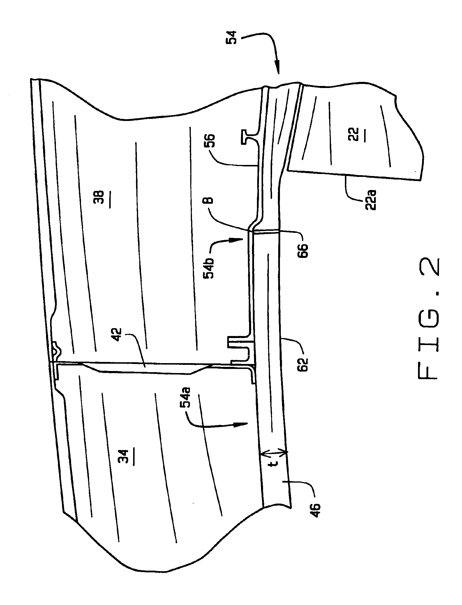
[0011]The nacelle 26 includes an inlet section 34 coupled to a main section 38 that supports the engine 14 and fan assembly 18 within an interior area of the nacelle 26. The junction between the inlet and main sections 34 and 38 includes a main bulkhead 42 that is used to give stru...


PUM


Abstract

An aircraft engine assembly is provided that is adapted to reduce noise produced by an engine included in the engine assembly. The engine assembly includes a nacelle having an inlet section and a main section that is houses the engine and fan assembly associated with the engine. The inlet section is coupled to the main section at a main bulkhead junction between the inlet section and the main section. A one piece annular acoustic panel is located within a recess in an internal wall of the nacelle. The annular acoustic panel extends from a forward portion of the inlet section to a forward portion of the main section such that the bulkhead is covered by the annular acoustic panel.

Description

FIELD OF INVENTION[0001]The invention relates generally to inlet absorption and attenuation of aircraft engine noise. More specifically, the invention relates to a monolithic annular acoustic panel that extends interiorly from a front portion of an engine nacelle inlet, past a junction of the nacelle inlet and a nacelle engine structure, and into the engine structure.BACKGROUND OF THE INVENTION[0002]Airlines are required by law to meet certain regulatory engine noise standards for their aircraft. Generally, known aircraft engine acoustic treatment systems consist of a segmented series of individual panels attached inside an engine fan case. The panels are typically located immediately aft of an engine / inlet attachment interface and forward of an engine fan assembly. At least one known engine acoustic treatment system includes multiple individual panels installed side by side around an interior surface of the engine fan case and / or other adjacent interior areas of an engine nacelle. ...

Claims


Application Information

Patent Timeline
Patent Type & Authority Patents(United States)
IPC IPC(8): B64D29/00B64D33/02B64D33/00F02C7/045F02K1/82F02C7/04F02K1/00
CPCB64D29/00B64D33/02F02C7/045F02K1/827B64D2033/0206Y02T50/672F05D2260/96Y02T50/60
Inventor HARRISON, GEOFFREY E.
Owner THE BOEING CO
Why Eureka
Try Eureka