Method and apparatus for performing a magnetic pulse welding operation

a technology of magnetic pulse welding and welding operation, which is applied in the field of magnetic pulse welding techniques, can solve the problems of achieving the necessary high velocity impact, the fixture is relatively difficult to set up and maintain, and the permanent joining of the two components, etc., and achieves the effects of improving the control of the magnetic pulse welding process, and reducing the difficulty of welding

Inactive Publication Date: 2005-07-26
METALSA SA DE CV
View PDF8 Cites 22 Cited by
  • Summary
  • Abstract
  • Description
  • Claims
  • Application Information

AI Technical Summary

Benefits of technology

[0005]This invention relates to an improved method and apparatus that automatically and co-axially aligns two components, such as a pair of metallic structural components of a vehicle frame assembly, prior to full energization of the magnetic pulse welding inductor to provide for improved control of the magnetic pulse welding process. To accomplish this, either or both of the components are supported in a floating manner, i.e., a manner in which either or both of such components are free to move relative to one another, at least to a limited extent. An electromagnetic coil is then partially energized so as to generate a magnetic field of relatively small intensity within or about one of the components. This relatively small intensity magnetic field exerts a relatively small force on the two components, causing them to move to a co-axially aligned position relative to one another and to the coil. Then, while the components are co-axially aligned, they are subjected to a magnetic field of relatively large intensity for the purpose of permanently joining such components together. This relatively large intensity magnetic field exerts a large pressure on one of the two components, causing it to deform toward the other of the two components at a high velocity. The high velocity impact of these two components, as well as the large pressures exerted thereon, caused the two components to become permanently joined together. If desired, the preliminary low intensity magnetic field can also be used to preliminarily heat the two components in the nature of induction heating. This can be accomplished by maintaining the preliminary low intensity magnetic field for a predetermined period of time beyond that which is necessary to effect the co-axial alignment of the components. Such preliminary heating of the two components can soften them somewhat in order to facilitate the subsequent performance of the magnetic pulse welding operation. As a result of such softening, the amount of energy that is consumed during the magnetic pulse welding operation may be reduced.

Problems solved by technology

If a non-uniform gap is provided between the two components when they are subjected to the intense magnetic field, the some portions thereof may not achieve the necessary high velocity impact that is necessary to cause permanent joining of the two components.
However, such fixtures have been found to be relatively difficult to set up and maintain, particularly when the two components are relatively large or heavy.

Method used


Image

  • Method and apparatus for performing a magnetic pulse welding operation
  • Method and apparatus for performing a magnetic pulse welding operation
  • Method and apparatus for performing a magnetic pulse welding operation

Examples


Embodiment Construction

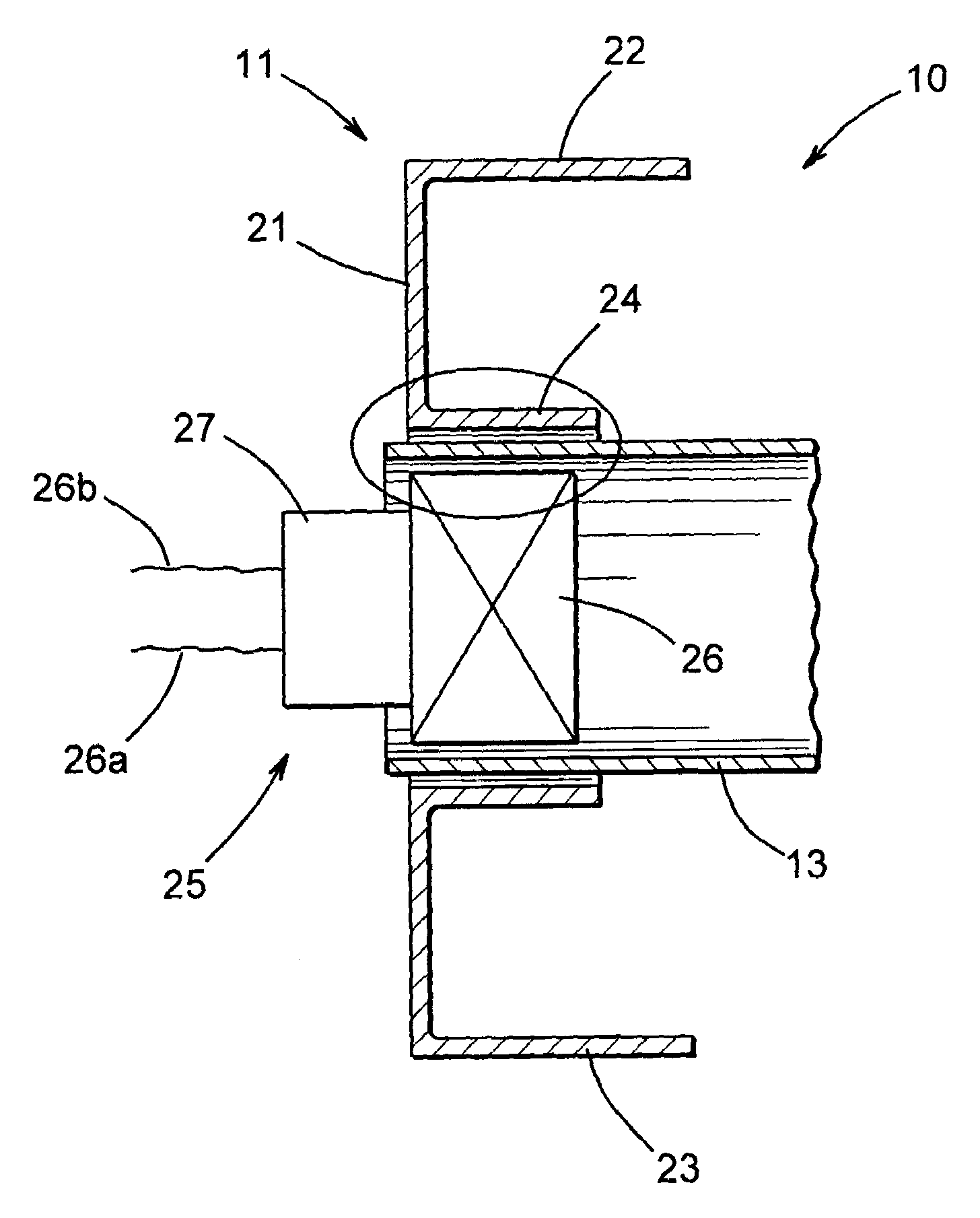
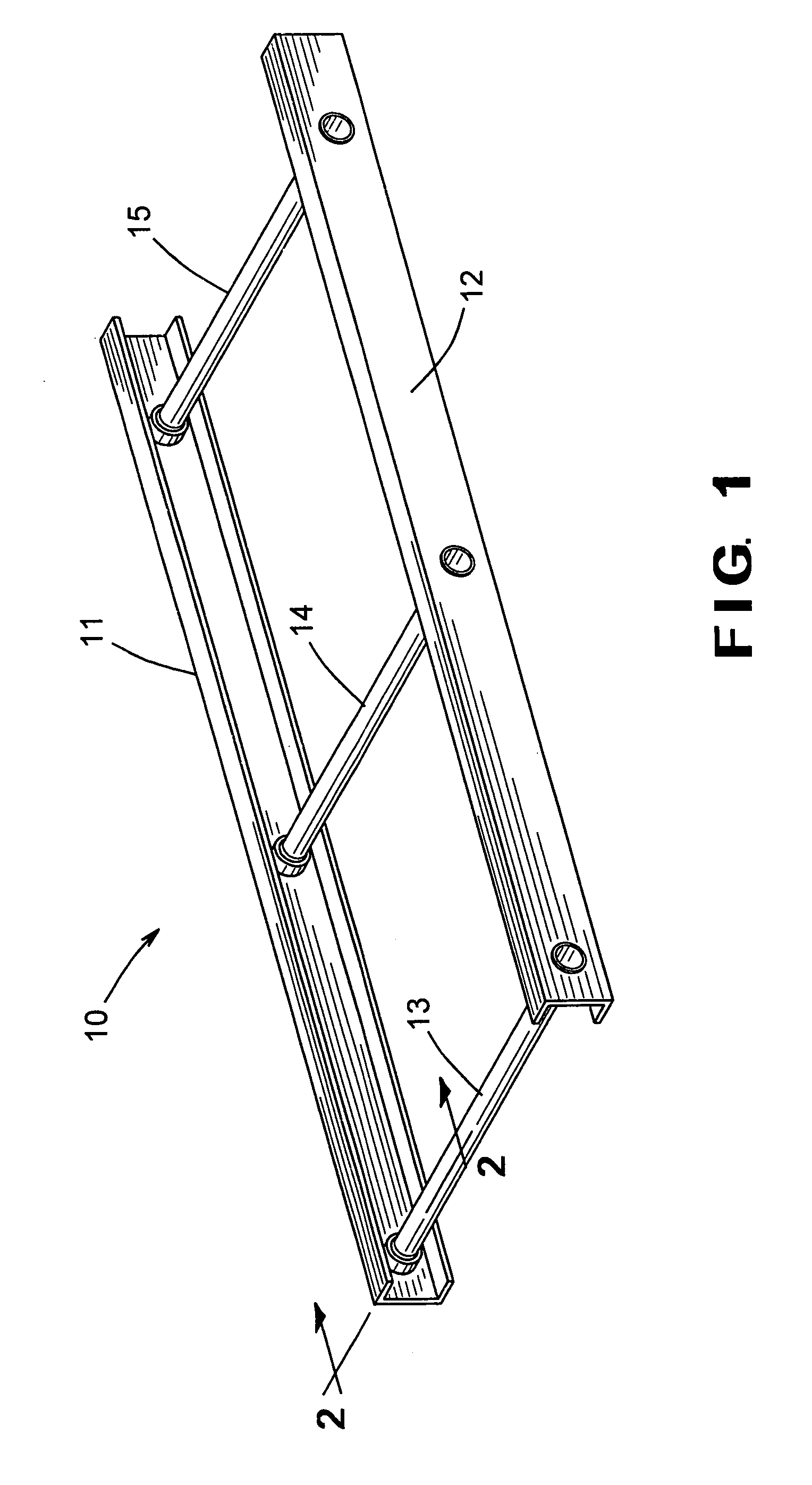
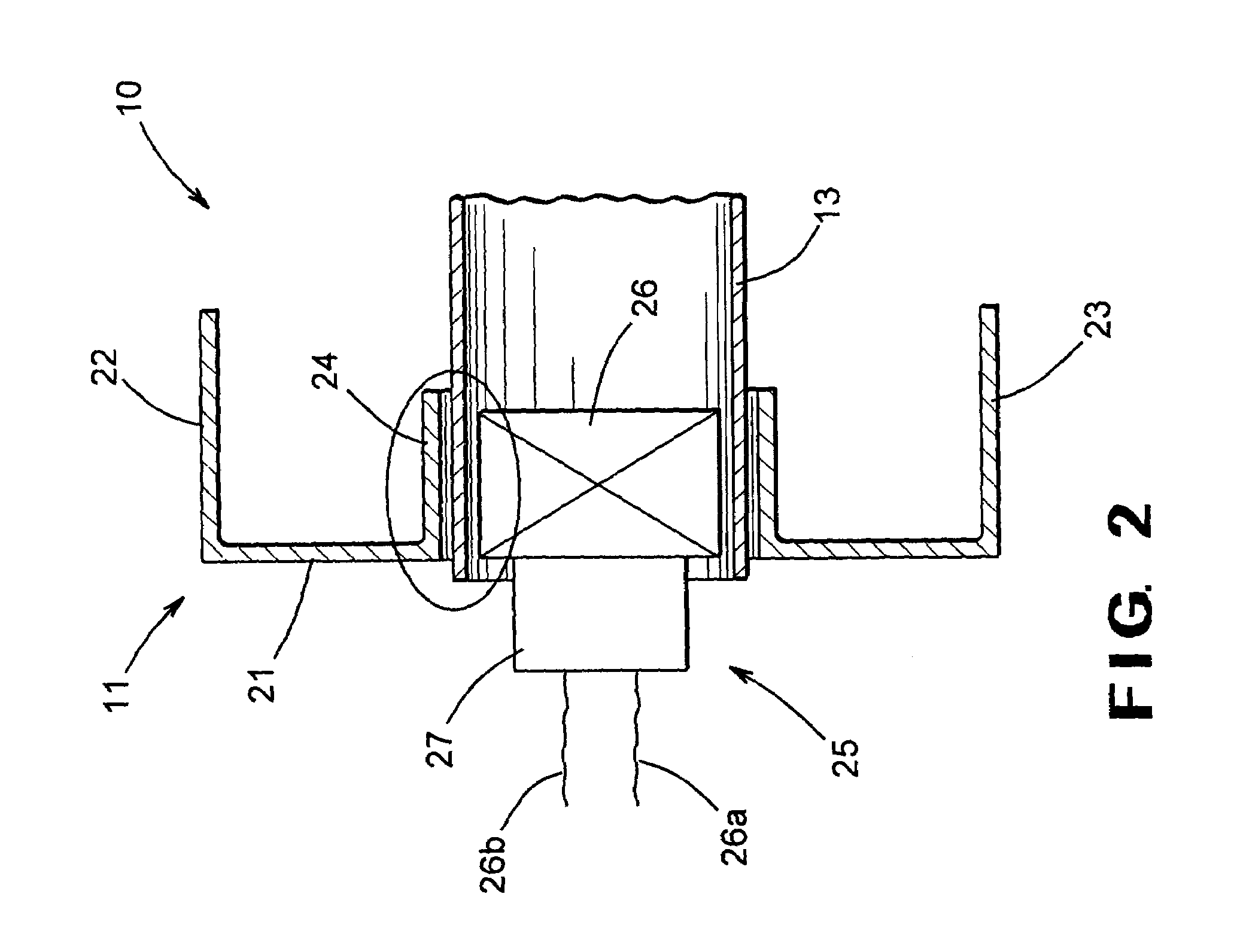
[0014]Referring now to the drawings, there is schematically illustrated in FIG. 1 a first embodiment of a vehicle body and frame assembly, indicated generally at 10, that has been manufactured in accordance with the apparatus and method of this invention. The illustrated vehicle body and frame assembly 10 is a ladder frame assembly. However, it will be appreciated that the apparatus and method of this embodiment of the invention may be utilized in the manufacture of any type of vehicle body and frame assembly, such as a unitized body and frame assembly where the structural components of the body portion and the frame portion are combined into an integral unit, as discussed above. Furthermore, although this invention will be described in the context of the illustrated vehicle body and frame assembly 10, it will be appreciated that this invention can be used to secure any type of metallic components together.

[0015]The illustrated ladder frame assembly 10 includes a pair of longitudina...


PUM

PropertyMeasurementUnit
magnetic fieldaaaaaaaaaa
pressureaaaaaaaaaa
velocityaaaaaaaaaa

Abstract

A pair of metallic components are co-axially aligned prior to full energization of the magnetic pulse welding inductor to provide for improved control of the magnetic pulse welding process. To accomplish this, either or both of the components are supported in a floating manner. An electromagnetic coil is then energized so as to generate a magnetic field of relatively small intensity within or about one of the components. This relatively small intensity magnetic field exerts a relatively small force on the two components, causing them to move to a co-axially aligned position relative to one another and to the coil. Then, while the components are co-axially aligned, they are subjected to a magnetic field of relatively large intensity for the purpose of permanently joining such components together. This relatively large intensity magnetic field exerts a large pressure on one of the two components, causing it to deform toward the other of the two components at a high velocity. The high velocity impact of these two components, as well as the large pressures exerted thereon, caused the two components to become permanently joined together.

Description

CROSS REFERENCE TO RELATED APPLICATION[0001]This application claims the benefit of U.S. Provisional Application No. 60 / 369,979, filed Apr. 4, 2002, the disclosure of which is incorporated herein by reference.BACKGROUND OF THE INVENTION[0002]This invention relates in general to magnetic pulse welding techniques for permanently joining two metallic components, such as a pair of structural components for a vehicle frame assembly. In particular, this invention relates to an improved method and apparatus for performing a magnetic pulse welding operation that automatically and co-axially aligns the two components relative to one another and to a magnetic pulse welding inductor prior to full energization of the inductor for improved control of the magnetic pulse welding process.[0003]Magnetic pulse welding is a well known process that can be used to permanently join two metallic components, such as a pair of structural components of a vehicle frame assembly. Typically, a magnetic pulse wel...

Claims


Application Information

Patent Timeline
Patent Type & Authority Patents(United States)
IPC IPC(8): B23K20/06
CPCB23K20/06B23K2201/06B23K2101/06
Inventor KICHLINE, JR., JOHN L.POIRIER, JASON A.
Owner METALSA SA DE CV
Why Eureka
Try Eureka