Foamed and stretched plastic bottle

a technology of plastic bottles and foils, applied in the direction of containers preventing decay, machines/engines, other domestic objects, etc., can solve the problems of insufficient light-shielding properties, difficult to maintain transparency in recycled resins, and inability to add coloring agents, etc., to achieve excellent light-shielding properties without decreasing strength, maintain high degree of light-shielding properties, and reduce the thickness of the body portion of the bottl

Active Publication Date: 2017-07-04
TOYO SEIKAN GRP HLDG LTD
View PDF39 Cites 0 Cited by
  • Summary
  • Abstract
  • Description
  • Claims
  • Application Information

AI Technical Summary

Benefits of technology

The present invention relates to a foamed and stretched plastic bottle with improved light-shielding properties. The foamed cells in the bottle have a unique distribution of lengths, which results in high light-shielding without compromising the strength of the bottle. The foam cells can have a gradational distribution, where their length gradually decreases towards the inner surface of the bottle and increases towards the outer surface. This distribution of lengths helps to maintain a high level of light-shielding property and ensures a high degree of mirror gloss. Additionally, the foaming process can occur in a controlled and targeted manner to improve the distribution and size of the foamed cells.

Problems solved by technology

From the standpoint of reutilizing the resources, however, adding the coloring agent is not desired (since it makes it difficult to maintain transparency in the recycled resins).
With the formed body in which the average diameter of the foamed cells is changing as proposed by the patent document 1, however, a non-foamed portion (where no foamed cell is present) is thickly formed in the central portion thereof, and light-shielding property is not attained to a sufficient degree.
According to this means, however, foamed cells of very large sizes are distributed in the central portion of the body portion causing the strength to be very decreased due to the foaming and making it difficult to put it into practical use.
In the container of the patent document 2, however, the size of the foamed cells decreases progressively toward the inner surface side of the container still leaving a problem of a decrease in the light-shielding property despite the foamed cells are formed.
Therefore, multiplex reflection is not so much attained by the foamed cell-containing portion, and the light-shielding property tends to decrease conspicuously.
If foaming is promoted to compensate for it, then the bubbles become coarse on the outer surface side making it difficult to attain a high mirror gloss and, therefore, leaving room for improvements.
That is, either the patent document 2 or 3 has the foamed cells of a flat shape but also has a problem in that the mirror gloss is lost as the number of the foamed cells increases.

Method used


Image

  • Foamed and stretched plastic bottle
  • Foamed and stretched plastic bottle
  • Foamed and stretched plastic bottle

Examples


experimental example 1

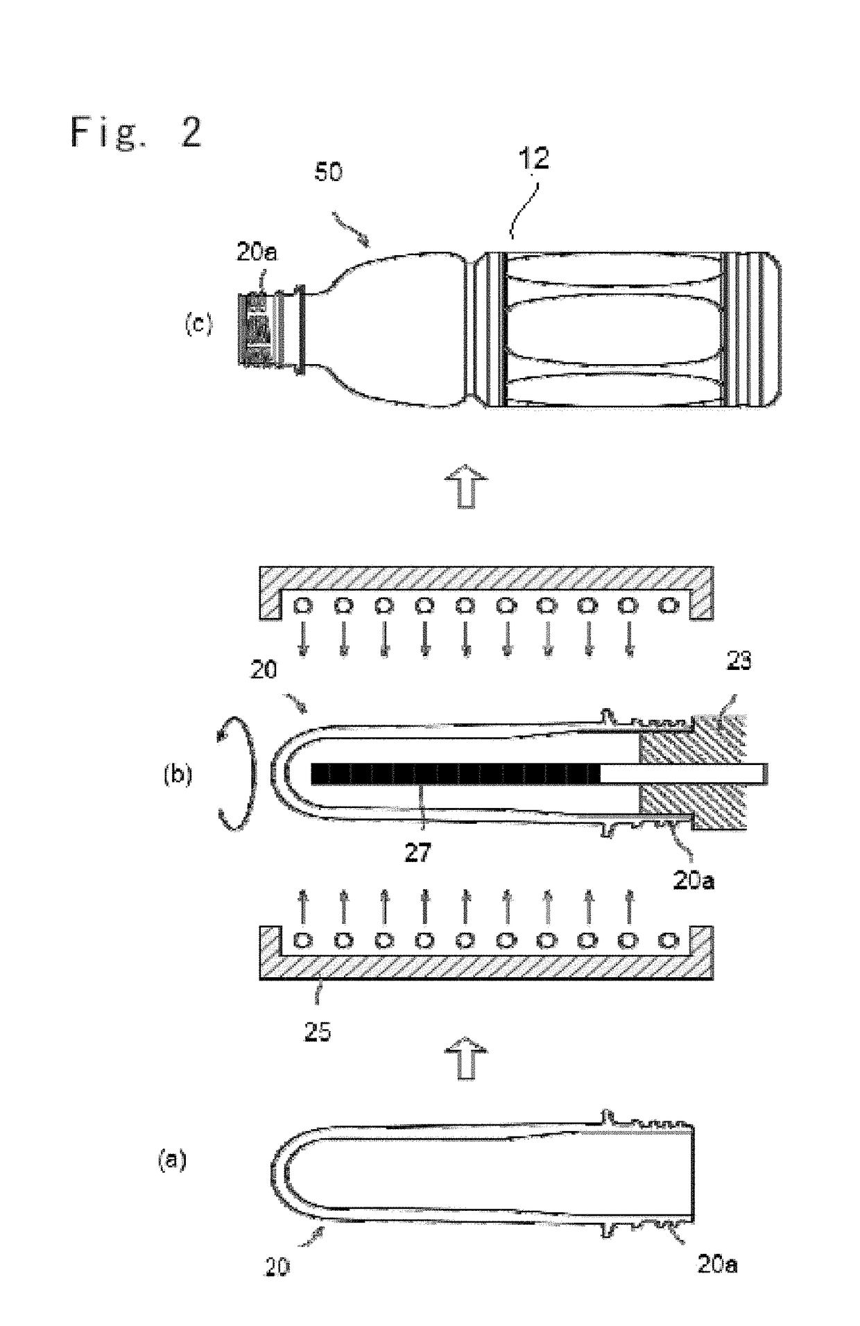
[0136]A commercially available PET resin (intrinsic viscosity: 0.84 dl / g) for bottle sufficiently dried by using desiccator / drier was fed into a hopper of an injection-forming machine. Further, a nitrogen gas was fed in an amount of 0.15% by weight through the middle of the heating cylinder of the injection-forming machine, and was kneaded with the PET resin so as to be dissolved therein. In order to suppress the foaming in the mold, the pressure in the mold had been elevated in advance with the air (pressure in the mold, 5 MPa) and while adjusting the pressure therein so will not to permit the foaming (pressure of 50 MPa for 12 seconds until injected), the PET resin was injected-formed to obtain a container preform (weight, 31.6 g) of the shape of a test tube imbibing the gas.

[0137]The gas-imbibing preform was heated from the outer surface side thereof by using a quartz heater and was heated from the inner surface side thereof by inserting therein an iron core heated by high freque...

experimental example 2

[0141]A gas-imbibing preform was prepared under the same conditions as those in Experimental Example 1, and from which a foamed bottle was formed in the same manner as in Experimental Example 1 but elevating the temperature of the iron core. The temperature just before the blowing was 107° C. on the outer surface and 118° C. on the inner surface.

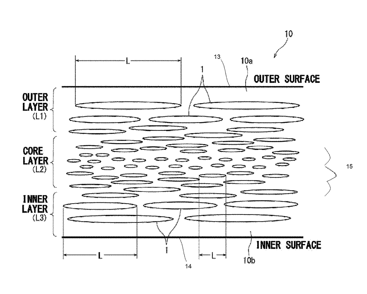
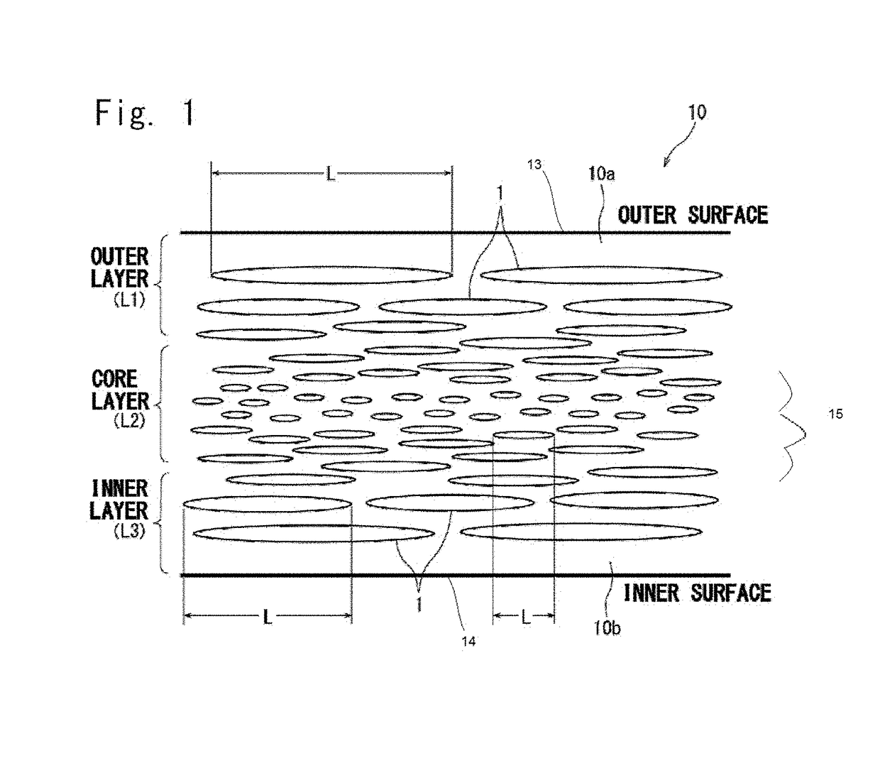
[0142]By using the SEM, the foamed bottle was observed in the same manner as in Experimental Example 1 and was measured for its distribution of cell diameters to learn that a number of flat cells had been formed in the wall of the bottle. The average lengths of the foamed cells in the axial direction of the bottle were 33.03 μm in the outer layer, 24.96 μm in the core layer and 34.81 μm in the inner layer. Namely, there had been formed the foamed cells having the same length distribution as that of Experimental Example 1. The foamed cells occupied the foamed region at an area ratio of 19.0%. The average number of the cells was 53.0 in the di...

experimental example 3

[0143]A gas-imbibing preform was prepared under the same conditions as those in Experimental Example 1, and from which a foamed bottle was formed in the same manner as in Experimental Example 1 but lowering the temperature of the iron core. The temperature just before the blowing was 103° C. on the outer surface and 90° C. on the inner surface.

[0144]By using the SEM, the foamed bottle was observed in the same manner as in Experimental Example 1 to confirm that there had been formed flat cells but in a small number. The average lengths of the foamed cells in the axial direction of the bottle were 33.27 μm in the outer layer, 12.34 μm in the core layer and 8.89 μm in the inner layer. Namely, there had been formed the foamed cells having such a gradational tendency that the foamed cell sizes gradually decreased from the outer surface side toward the inner surface side. The foamed cells occupied the foamed region at an area ratio of 4.8%. The average number of the cells was 10 in the di...


PUM

PropertyMeasurementUnit
average cell length L3aaaaaaaaaa
area ratioaaaaaaaaaa

Abstract

A foamed and stretched plastic bottle having, in the body portion thereof, a foamed region in which foamed cells are distributed, wherein, in at least a portion of the foamed region, the lengths of the foamed cells in the axial direction of the bottle are so distributed as to gradually decrease as the positions of the foamed cells shift from the outer surface side of the body portion toward the central portion thereof and then gradually increase as their positions shift from the central portion thereof toward the inner surface side thereof. The foamed and stretched plastic bottle of the invention exhibits excellent light-shielding property.

Description

TECHNICAL FIELD[0001]This invention relates to a foamed and stretched plastic bottle having, in a body portion thereof, a foamed region containing bubbles distributed therein.BACKGROUND ART[0002]Containers of a polyester as represented by polyethylene terephthalate (PET) feature excellent properties such as transparency, heat resistance, gas-barrier property and the like properties, and have been extensively used for a variety kinds of applications.[0003]In recent years, on the other hand, it is a mounting demand to reutilize the resources inclusive of the above polyester containers. Therefore, attempts have been made to recover the used containers and to reuse them as the recycled resin for various applications. Here, many of the contents contained in the packing containers are subject to be degraded with light, as represented by some kinds of beverages, medicines, cosmetics and the like. Therefore, these kinds of contents are provided being contained in opaque containers that are ...

Claims


Application Information

Patent Timeline
Patent Type & Authority Patents(United States)
IPC IPC(8): B65D1/40B65D1/02B29B11/08B65D81/30B29C49/06B29B11/14B29C49/08B29K105/04B29L31/00
CPCB65D1/0207B29B11/08B65D1/0223B65D1/40B65D81/30B29B11/14B29B2911/14013B29C49/06B29C49/08B29K2105/04B29L2031/7158B29C2949/20B29C49/071B29C2949/0715B29C2049/023F01N2310/10B29C49/086B29C49/12B29C49/6454B29K2067/003B29K2105/043
Inventor IINO, HIROKIICHIKAWA, KENTAROUKOISO, NOBUHISAAKUZAWA, NORIONOMURA, TETSURO
Owner TOYO SEIKAN GRP HLDG LTD
Why Eureka
Try Eureka