Fuel injection valve

a technology of fuel injection valve and fuel injection pump, which is applied in the direction of fuel injection pump, machine/engine, mechanical equipment, etc., can solve the problems of high production cost and high production complexity of sealing rings, and achieve the effect of convenient installation and cheap manufactur

Inactive Publication Date: 2005-07-26
ROBERT BOSCH GMBH
View PDF17 Cites 13 Cited by
  • Summary
  • Abstract
  • Description
  • Claims
  • Application Information

AI Technical Summary

Benefits of technology

[0004]The fuel injector according to the present invention has a sealing ring formed at a variable radius of cur...

Problems solved by technology

The fuel injector described in German Published Patent Application No. 196 00 403 has the disadvantage of high production complexity of the sealing rings.
Furthermore...

Method used


Image

  • Fuel injection valve
  • Fuel injection valve
  • Fuel injection valve

Examples


Embodiment Construction

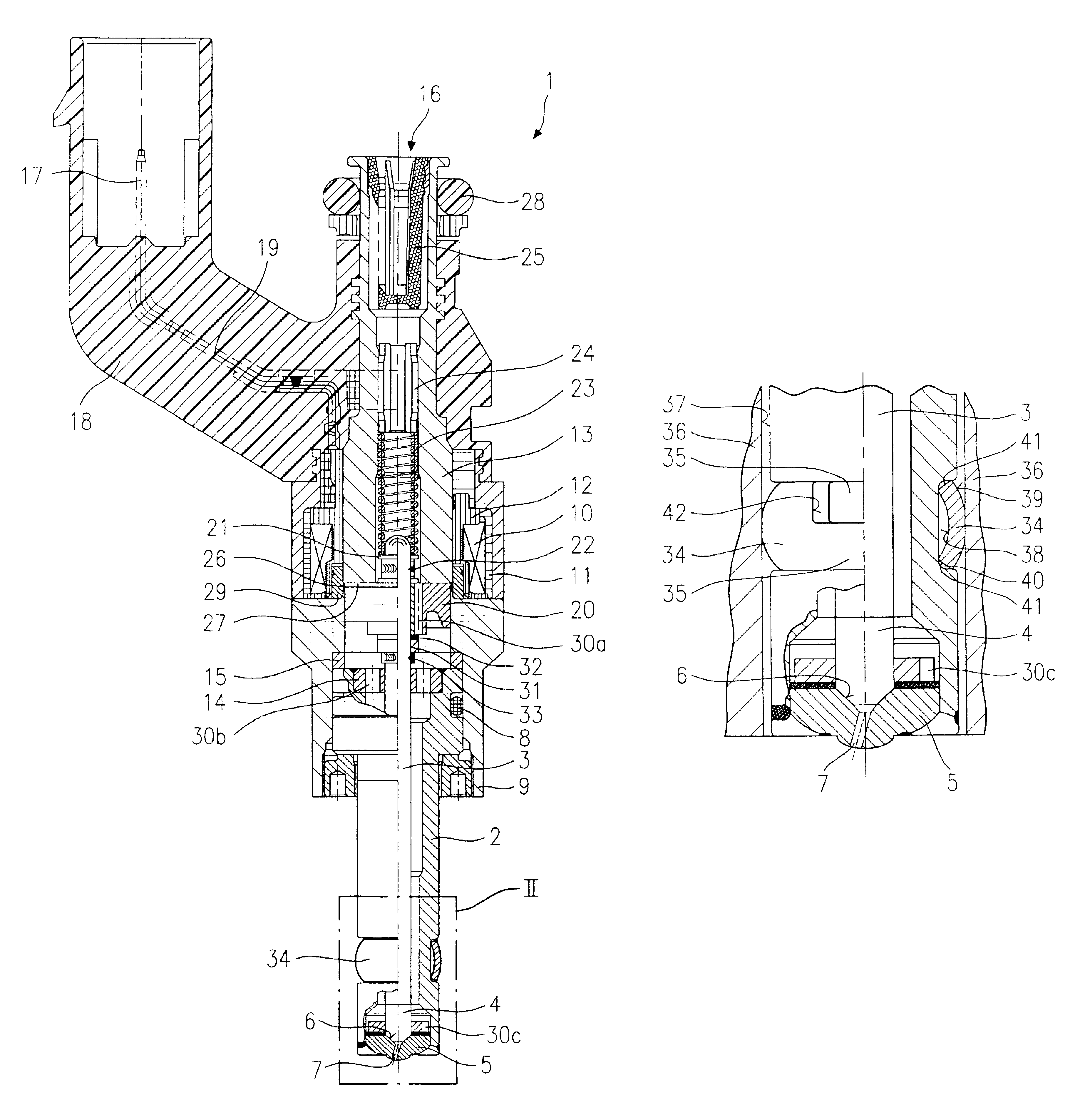
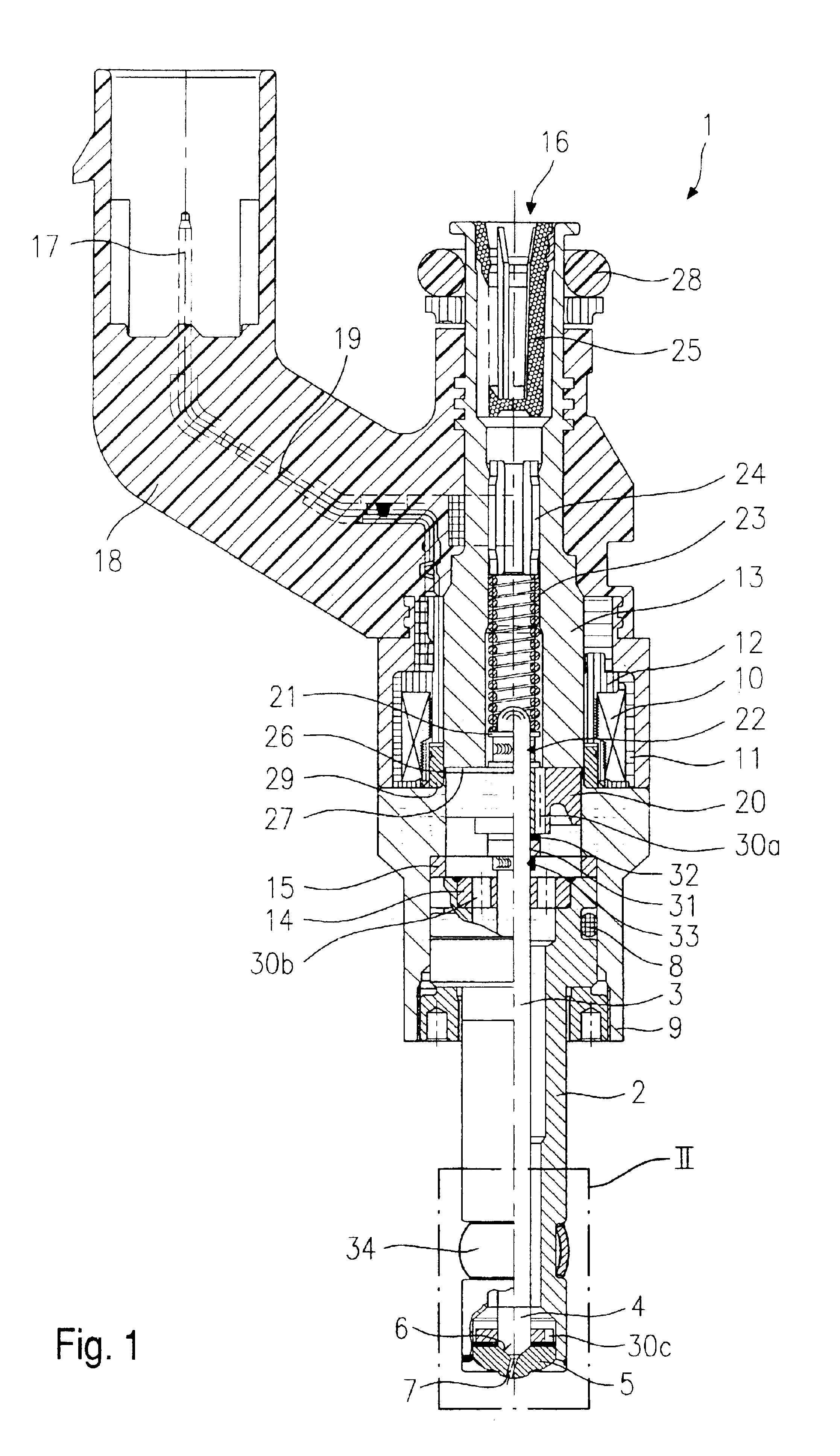
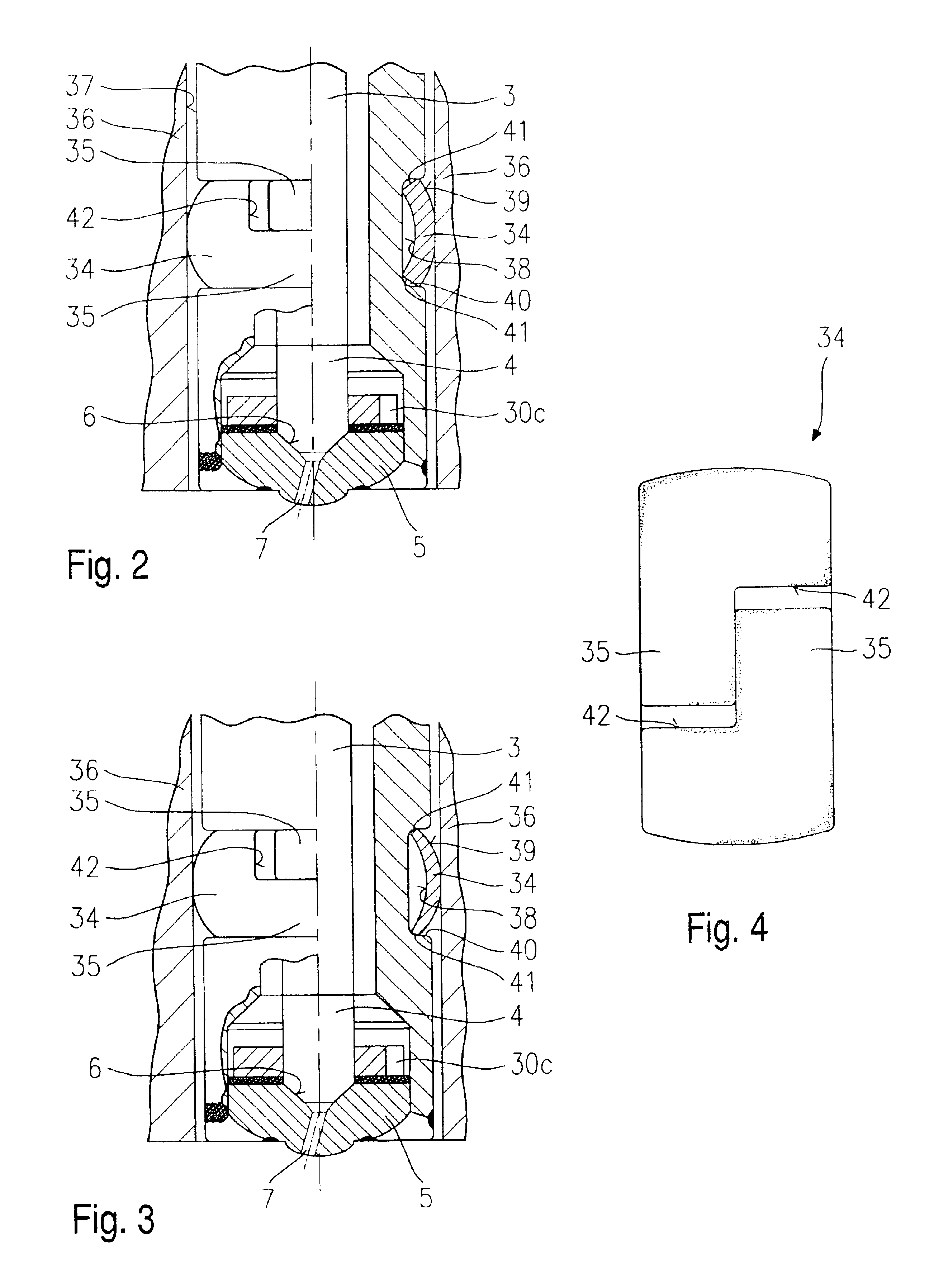
[0012]Before giving a more detailed description, based on FIGS. 2 through 4, of exemplary embodiments of a fuel injector 1 according to the present invention, to provide a better understanding of the present invention, a fuel injector 1 shall first of all be explained briefly in terms of its essential components with reference to FIG. 1.

[0013]Fuel injector 1 is designed in the form of a fuel injector for fuel-injection systems of mixture-compressing internal combustion engines with externally supplied ignition. Fuel injector 1 may be particularly suitable for the direct injection of fuel into a combustion chamber of an internal combustion engine.

[0014]Fuel injector 1 is made up of a nozzle body 2 in which a valve needle 3 is positioned. Valve needle 3 is in operative connection with a valve-closure member 4 that cooperates with a valve-seat surface 6, arranged on a valve-seat member 5, to form a sealing seat. In the example embodiment, fuel injector 1 is an inwardly opening fuel inj...


PUM


Abstract

A fuel injector, particularly for the direct injection of fuel into the combustion chamber of a mixture-compressing internal combustion engine having external ignition, include a valve housing formed by a nozzle body and a sealing ring which seals the fuel injector from a cylinder head of the internal combustion engine. The sealing ring has a convexly curved profile, two ends of the sealing ring axially overlapping one another in a stepped manner.

Description

FIELD OF THE INVENTION[0001]The present invention relates to a fuel injector for the direct injection of fuel into a mixture-compressing internal combustion engine.BACKGROUND INFORMATION[0002]German Published Patent Application No. 196 00 403 describes a conventional electromagnetic fuel injector and an appropriate structure for its mounting, which satisfy the requirements regarding the sealing effect, thermal resistance and pressure resistance for an internal combustion engine having direct fuel injection. Particular attention is paid in this context to sealing the area immediately adjacent to the cylinder where the electromagnetic fuel injector is mounted, as well as to a region more distant therefrom. As a result, according to the present invention, a first sealing section having a first sealing ring, which is configured as a wavy washer, is located close to the cylinder and between the fuel injector and the cylinder head. Moreover, a second sealing section having a second sealin...

Claims


Application Information

Patent Timeline
IPC IPC(8): F02M61/00F02M61/14F02M51/06F02M61/16F02F1/24
CPCF02M51/0671F02M61/14F02M2200/858
Inventor REITER, FERDINAND
Owner ROBERT BOSCH GMBH
Why Eureka
Try Eureka