Threaded joint for tubes

a technology of threaded joints and tubes, applied in the direction of flexible pipes, rigid pipes, pipe supports, etc., can solve the problems of galling, not enabling the high contact pressure generated, heavy metals are dangerous for health and the environment,

Active Publication Date: 2005-07-26
TENARIS CONNECTIONS
View PDF30 Cites 56 Cited by
  • Summary
  • Abstract
  • Description
  • Claims
  • Application Information

AI Technical Summary

Benefits of technology

[0025]The main purpose of the present invention is to eliminate the disadvantages referred to above.
[0027]An advantage obtained from the use of a dry lubricant applied on the parts co-operating in the joint at the end of the process of fabrication of the tubes is to prevent the need to carry out operations of lubrication during operation.
[0028]As a consequence of the fact that no space is required for containing excess lubricant, it is possible to optimize the geometry of the joint, the dimensions of the thread and the tolerances, reducing the empty spaces and consequently increasing the performance of the joint.
[0029]A further subject of the present invention is to optimize all the dimensions of the joint so as to reduce the total volume of the void space present therein.

Problems solved by technology

These heavy metals are dangerous for health and for the environment.
Apart from the risk of pollution, another problem that must be tackled is the determination of the quantity of lubricant, since performance of the joints is very sensitive to the variations of said quantity.
In general, galling occurs since an amount of lubricant less than the amount necessary does not ensure correct lubrication and does not enable the high contact pressure generated by the interference between the male and female threads to be sustained.
A problem opposite to the one described above is encountered in the use of dope and is the so-called “over-doping”, or excess of dope, which entails the difficulty, during screwing of a joint, of disposing of the excess dope at the ends of the threads of the segments of tube.
The entrapped dope can, as a result of this, develop high pressures in the joint.
In particular circumstances, such pressures are able to produce a plastic deformation of the pipe segments in the threaded portion, and may lead to the collapse of the pin member.
Entrapping occurs when the dope does not have sufficient space for penetrating the interstices of the thread, or else if there is not sufficient space for it to flow on the outside of the connection.
The above problem is even more serious in the case of a joint with more than one seal.
In this case, the lubricant is trapped between two seals, is not able to flow away, and it is impossible to reduce the high pressure that is developed.
The disadvantage resulting from providing a reservoir of lubricant consists in the creation of a considerable void space between the seals, which generates a loss of continuity and can thus reduce the performance of the joint.
Even if the lubricant is applied in a correct amount, the same problems referred to above may arise, mainly if there is a lack of uniformity of distribution over the entire area of the joint.
In this regard, it must be considered that the operation of application of the lubricant is carried out on the platform at the moment in which the string is lowered into the well and is consequently particularly expensive in terms of time and resources.
The frequently adverse environmental conditions render both the precise dosage of the amount of lubricant and its application on the threaded parts problematical.
Consequently, if we consider the quantities OD and ID of the tubes to be constant, said difference of 0.52 mm between the outside of the pin and the inside of the box can reduce the performance of the joint.
Furthermore, on account of the large gap on the stabbing sides of the thread, the threaded portion does not work when compressive loads are applied.

Method used


Image

  • Threaded joint for tubes
  • Threaded joint for tubes
  • Threaded joint for tubes

Examples


Embodiment Construction

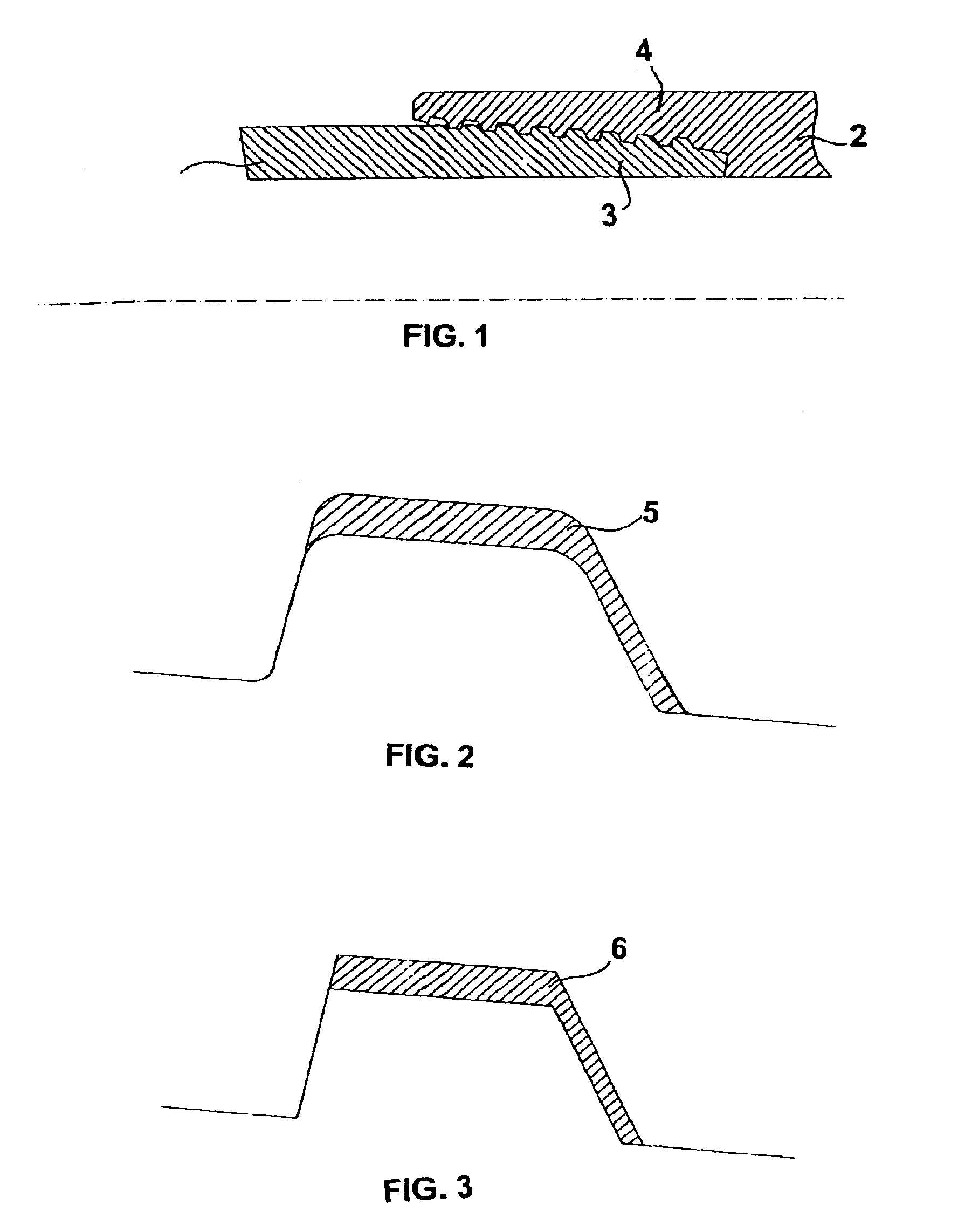
[0037]Illustrated in FIG. 1 is a joint comprising a male member or pin 1 with external thread 3 and a female member or box 2 with internal thread 4.

[0038]After accurate studies aimed at obtaining optimization in the sizing of the joints, it has proven possible to define mathematical relations between various parameters of the tubes.

[0039]We shall consider a thickness of coating of the dry lubricant of between 5 μm and 30 μm.

[0040]The area gT of the free space between the threads engaged in the section of the joint considered on an axial plane is less than 0.4 mm2 / pitch.

gT≦0.4 mm2 / pitch

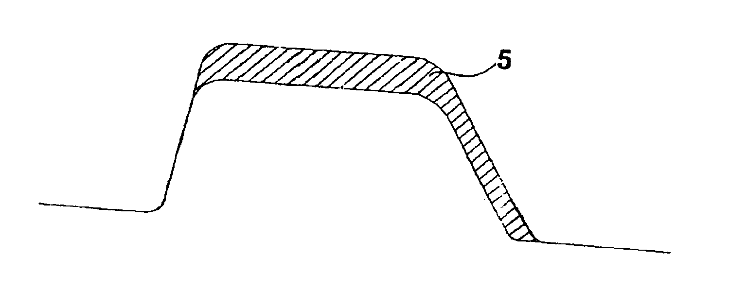
[0041]Said empty area gT, designated by the reference number 5, is represented in FIG. 2. It may be calculated, for example, with the aid of a CAD, or else considering the area 6 in the idealized form, as represented in FIG. 3.

[0042]If we consider a thread with 4 TPI and a tooth height of 1.5 mm, the area filled by a coating of 30 μm of thickness is approximately 0.3 mm2. Consequently, in order to prev...


PUM


Abstract

Described herein is a threaded joint, in which the threads are coated with a layer of dry lubricant having a thickness of between 5 μm and 30 μm and in which the nominal void volume NVV of the space (6, 7) between the thread of the male tube and the thread of the female tube, is sized by means of the following formulae: NVV⁡[cm3]≤4×OD⁡[inch]NVV⁡[cm3]OD⁡[inch]×Wt⁡[mm]≤1gT≤0.4⁢ ⁢mm2⁢ / ⁢pitchwhere OD is the nominal outer diameter and Wt is the thickness of the wall of the pipes.

Description

BACKGROUND OF INVENTION[0001]1. Field of the Invention[0002]The present invention relates to a threaded joint for joining tubes used, in particular, in the natural-gas and oil extraction industry, which has the characteristics of claim 1. Said tubes can be used both as pipes for pumping gas or oil, and as casings of the drilling wells themselves.[0003]2. Description of the State of the Art[0004]In oilfields it is common practice to use metal pipes of a definite length, joined to form a string such as to reach the depth at which the reservoirs of gas or oil are found for extraction of the latter.[0005]This extraction technique calls for the gradual internal coating of the well, in the course of drilling, using metal tubes, the so-called “casing”. Once the desired depth has been reached, a string of metal tubes of smaller diameter, the so-called “tubing”, is inserted in the “casing”, for pumping the liquid or gas hydrocarbons to the surface. Both the column for the casing and the colu...

Claims


Application Information

Patent Timeline
Patent Type & Authority Patents(United States)
IPC IPC(8): F16L15/00
CPCF16L15/001F16L15/002F16L15/003
Inventor MOROTTI, MATTEODELL'ERBA, DIEGOPINA, GIUSEPPE DELLA
Owner TENARIS CONNECTIONS
Why Eureka
Try Eureka