Laser centering mechanism of a drilling machine

Inactive Publication Date: 2005-07-26
SEAN & STEPHEN
View PDF12 Cites 34 Cited by
  • Summary
  • Abstract
  • Description
  • Claims
  • Application Information

AI Technical Summary

Benefits of technology

[0007]It is a main object of the present invention to provide a laser centering mechanism to a drilling machine, which consists of two laser modules capable of emitting laser lights forming two intersecting light lines on a workpiece for helping the drill of the drilling machine to be centered on a predtermined point of a workpiece, on which a hole is to be drilled, and which is fitted around a drill chunk so that only a light point at the intersection of the light lines is left visible when the drill is rotating.
[0008]The laser centering mechanism includes a clamp ring fitted around a drill chunk, upper and lower knobs, and two laser modules. The clamp ring has several spaced upwards-sticking flexible plates, and several

Problems solved by technology

Both of the above ways is not very convenient to use because the operator has to watch carefully to establish whether the drill is centered on the shallow mark while he is ope

Method used


Image

  • Laser centering mechanism of a drilling machine
  • Laser centering mechanism of a drilling machine
  • Laser centering mechanism of a drilling machine

Examples


Embodiment Construction

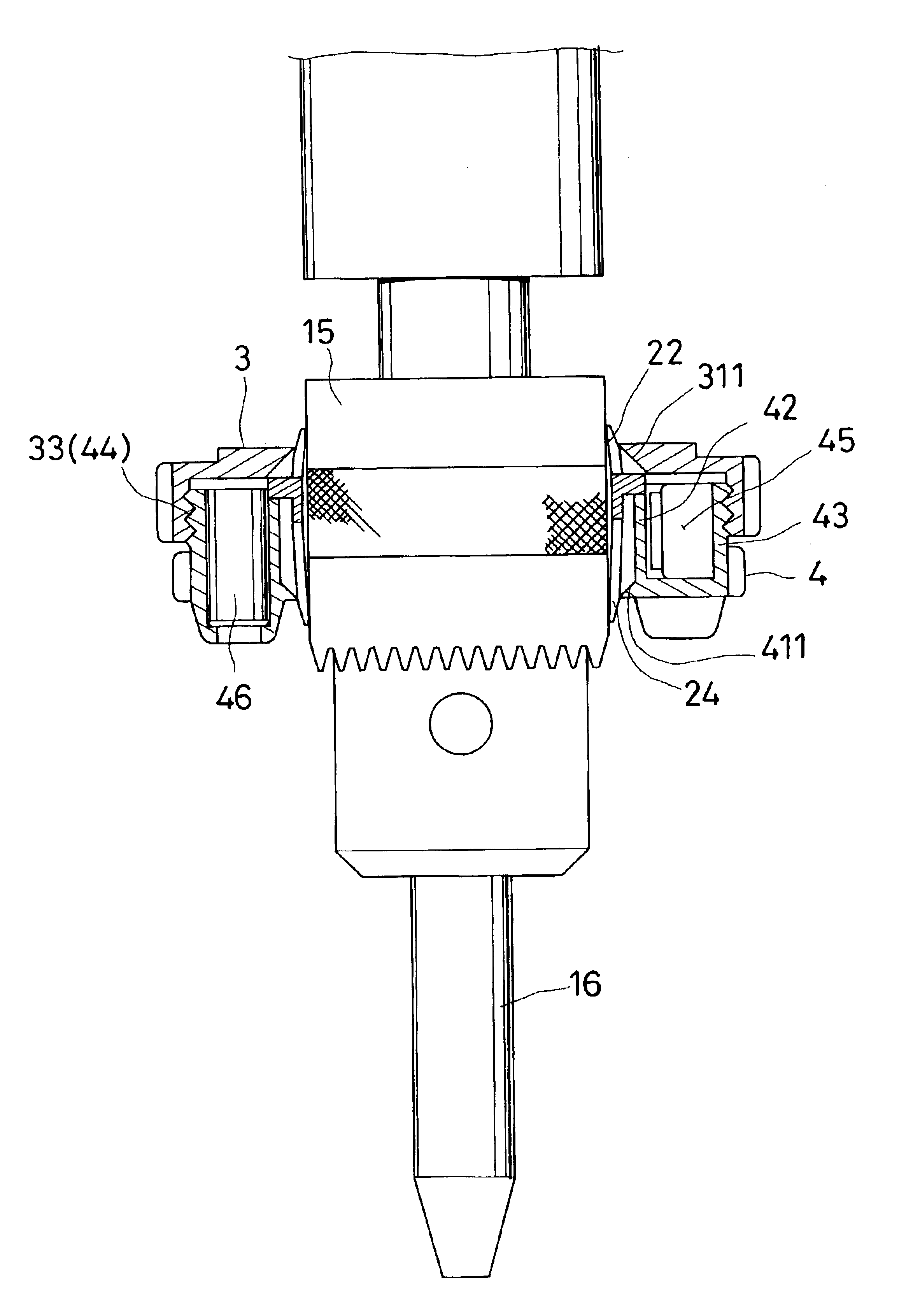
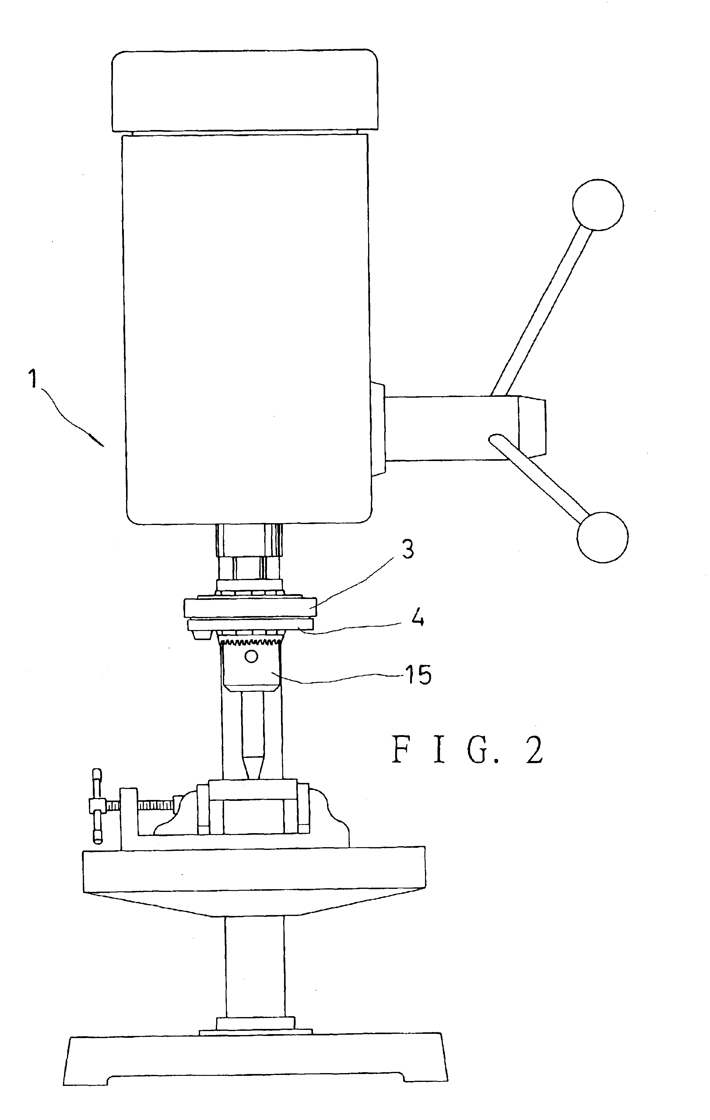
[0015]Referring to FIGS. 2, and 3, a laser centering mechanism (A) of a drilling machine according to the present invention includes a clamp ring 2 to be securely fitted around a drill chunk 15 of a drilling machine, two laser modules 46, 46, an upper knob 3, and a lower knob 4.

[0016]The clamp ring 2 has a through hole 25 defined by a middle portion (not numbered), several spaced upper flexible plates 22 extending from the upper side of the middle portion, and several spaced lower flexible plates 24 extending from the lower side of the middle portion; gaps 21 are provided between the flexible plates 22; gaps 23 are provided between the flexible plates 24. The upper flexible plates 22 each tapers from a middle towards an upper end thereof to have a sloping surface 221 on an outer side of an upper end portion thereof, and the flexible plates 24 each tapers from a middle towards a lower end thereof to have a sloping surface 241 on an outer side of a lower end portion thereof.

[0017]The ...


PUM

PropertyMeasurementUnit
Flexibilityaaaaaaaaaa

Abstract

A laser centering mechanism of a drilling machine includes a clamp ring fitted around a drill chunk of a drilling machine, upper and lower knobs, and two laser modules. The clamp ring has several spaced upwards-sticking flexible plates, and several downwards-sticking flexible plates. The knobs are fitted around an upper end, and a lower end of the clamp ring respectively. The knobs are securely screwed to each other so that inner annular portions thereof make corresponding flexible plates tightly and securely pressed against the drill chunk. The laser modules are fixed to an inner edge of the lower knob, and are equipped with such lenses that laser lights emitted therefrom form intersecting straight light lines on a plane under them, which will form a centering light point on a central axis of the lower knob in rotation of the present mechanism together with the drill chunk.

Description

BACKGROUND OF THE INVENTION[0001]1. Field of the Invention[0002]The present invention relates to a laser centering mechanism of a drilling machine, more particularly one, which is secured to a drill chunk of a drilling machine, and which consists of two laser modules capable of emitting laser lights forming two intersecting lines on a workpiece for helping a drill of the drilling machine to be centered on a predetermined point of the workpiece, on which a hole is to be drilled; only the intersection of the perpendicularly intersecting lines can be seen when the drill is rotating due to persistence of vision.[0003]2. Brief Description of the Prior Art[0004]Referring to FIG. 1, a conventional drilling machine has a support base 11, a support rod 12 joined to the base 11, and a table 13 supported on the support rod 12 for a workpiece 10 to be positioned on; fixing jaws 19 are disposed on the table 12 for fixing the workpiece 10 in position; a power source 14 is disposed above the table...

Claims


Application Information

Patent Timeline
IPC IPC(8): B23Q17/24B23B49/00
CPCB23B49/00B23Q17/24Y10T408/21Y10T408/175
Inventor CHEN, SEAN
Owner SEAN & STEPHEN
Why Eureka
Try Eureka