
Dual-sided, texturized biocompatible structure

a biocompatible, dual-sided technology, applied in the field of implantable tissue expanders, can solve the problems of prohibitively expensive, difficult to create a normal teardrop shaped and normally pendant breast, and commercially considered less than desirabl

Inactive Publication Date: 2005-07-26
LEDERGERBER WALTER J
View PDF39 Cites 56 Cited by
  • Summary
  • Abstract
  • Description
  • Claims
  • Application Information

AI Technical Summary

Benefits of technology

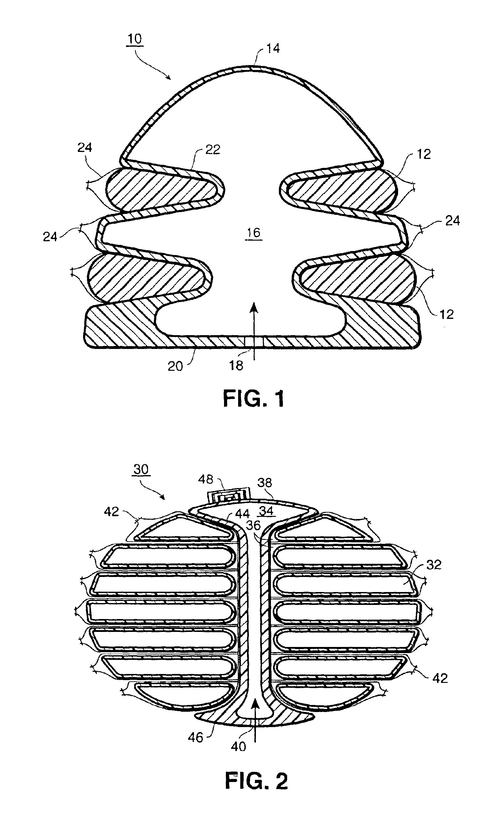
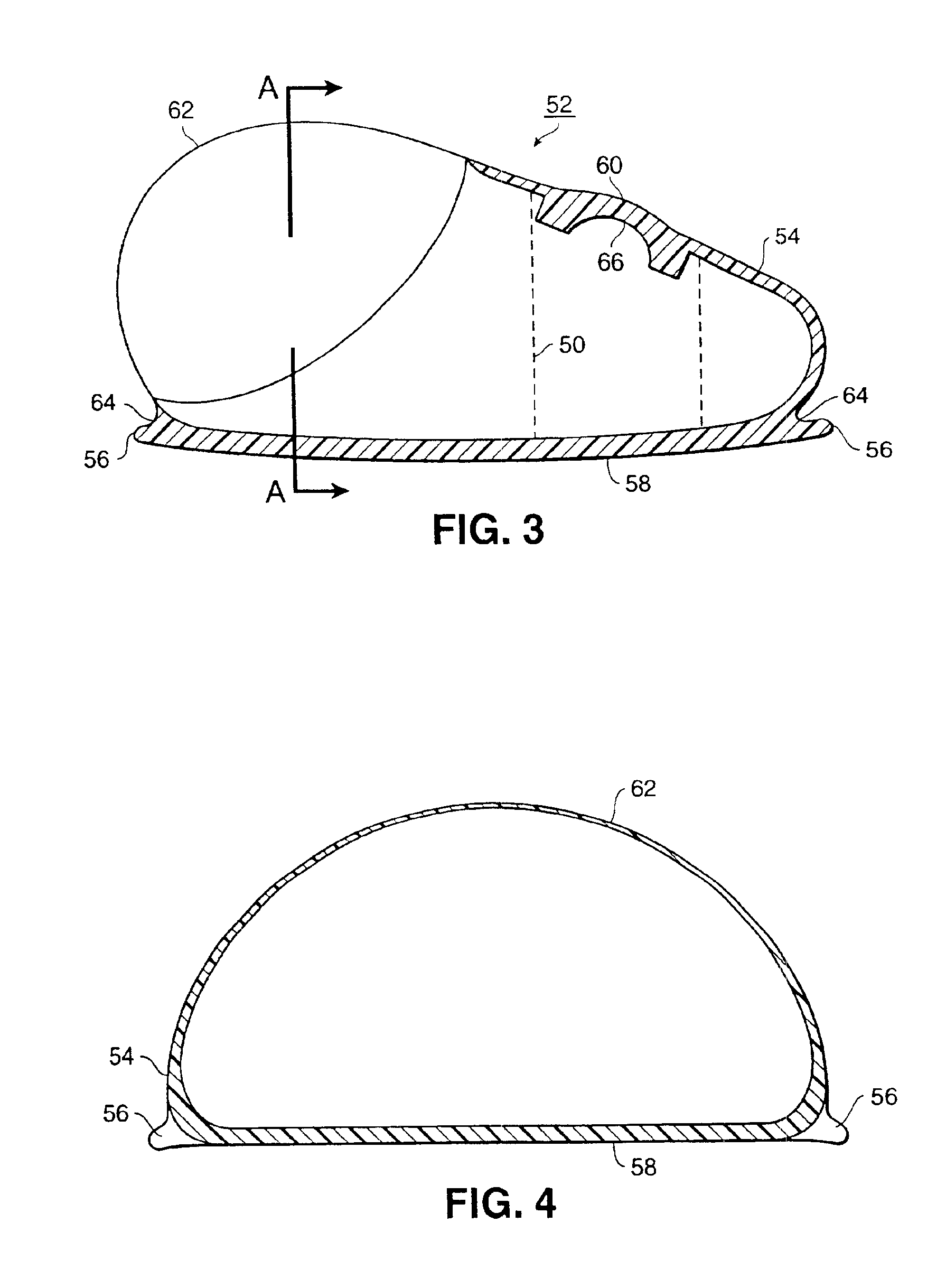
[0008]The base may include ribs or other molded-in structures to increase structural integrity. Additionally, the base may include “toes” or other structures which project out from the base, such as flanges, which are adapted to provide a broader base or footprint to the expander. The expander enjoys increased base and dimensional stability as a consequence.
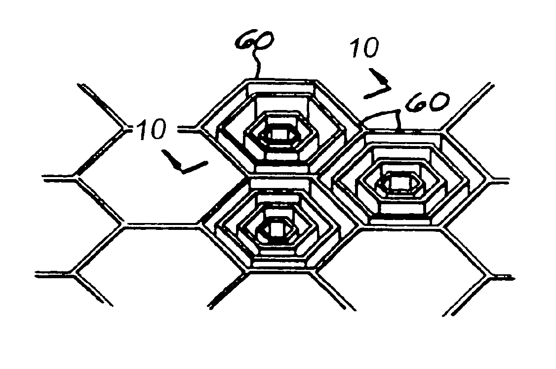
[0010]Molded-in geometric patterns may be employed to present varying textured surfaces to the internal or external surfaces of the implant or expander. This results in increased soft tissue purchase by virtue of unique surface topography and assists in obtaining differential expansion by virtue of the differential purchase resulting from the different molded-in patterns. Textured surfaces also have the effect of weakening periprosthetic scar tissue. Optionally, compressive structures may be beneficially used on the surface of the implant or in the interior of the implant.
[0013]It is a further object of this invention to provide an enhanced ability to weaken periprosthetic scar as well as to permit the surgeon to improve cavity contour at the end of the expansion phase.
[0014]It is yet a further object of this invention to create variable yet controlled purchase at the tissue / expander interface and to provide for differential expansion capability by varying wall thickness. It is another object of this invention to provide for directional expandability of the expander.
[0016]It is a further object of this invention to provide an implantable prosthesis which permits postimplantation accommodation of total volume, either more or less than the volume at implantation.

Problems solved by technology

In breast reconstruction, major problems associated with the tissue expansion process include difficulty in creating a normal teardrop shaped and normally pendant breast due to the inability to create a properly shaped pocket.
These are commercially considered less than desirable because they are prohibitively expensive.
They are functionally suboptimal as slippage at the soft tissue / expander interface may occur and there is a lack of purchase at the interface which is associated with inappropriate thinning and grossly non-uniform expansion of tissue.

Method used


Image

  • Dual-sided, texturized biocompatible structure
  • Dual-sided, texturized biocompatible structure
  • Dual-sided, texturized biocompatible structure

Examples


Embodiment Construction

[0031]The present invention is based upon the previously disclosed method of liquid silicone molding of textured implants (my U.S. Pat. No. 5,354,338), directional expansion of implants and varying wall thickness (my U.S. Pat. No. 4, 955, 907), pressure adaptive structures, (my U.S. Pat. No. 5,383,929), as well as novel elements disclosed herein and methods of manufacture of the combination of elements.

[0032]The term implant is used broadly to include any foreign object which is inserted into the body. An expander is an object which is an implant because it is placed within the body. An expander is ordinarily placed within the body, and over time, such as a matter of weeks or a few months, is gradually inflated so as to expand and move adjacent soft tissues. After expansion, the expander may be removed from the body and the space filled with another implant, or optionally, the expander may be converted into a permanent implant in the body. In the latter case, this may involve changi...


PUM

PropertyMeasurementUnit
Thicknessaaaaaaaaaa
Widthaaaaaaaaaa

Abstract

A soft tissue expander has enhanced performance through use of differential and directional expandability, continuous expansion capability, increased base and dimensional stability, increased soft tissue purchase by virtue of unique surface topography, and results in improved cavity contour after expansion. Expansion means may be provided to expand the implant in a desired direction. In the preferred embodiment, an expander or implant has an exterior surface defining a volume, the exterior surface including a base portion, a first wall and a second wall, wherein the second wall is relatively thinner than the first wall. A fill port, which may be integrally molded into the expander, is included. As the expander is inflated, differential expansion occurs with the relatively thin second wall section expanding more than that of the first wall section. The base may include ribs or other molded-in structures to increase structural integrity. Optionally, a bellows may be included on the exterior surface of the expander, the bellows optionally including a limiting ring. Molded-in geometric patterns may be employed to present textured internal, as well as external surfaces to the implant or expander. Compressive structures may be used on the inside or outside surface of the implant.

Description

CROSS REFERENCE TO RELATED APPLICATIONS[0001]This application is a continuation of U.S. application Ser. No. 08 / 823,119, filed on Mar. 25, 1997, now U.S. Pat. No. 6,228,116, which is a file wrapper continuation of U.S. application Ser. No. 08 / 472,781, filed on Jun. 7, 1995, now abandoned, which is a continuation-in-part of application U.S. Ser. No. 08 / 198,651, filed on Feb. 18, 1994, now U.S. Pat. No. 5,653,755, which is a continuation of U.S. application Ser. No. 07 / 837,284, filed on Feb. 18, 1992, now abandoned, which is a continuation of U.S. application Ser. No. 07 / 137,871, filed on Dec. 22, 1987, now U.S. Pat. No. 5,282,856, and is related to application Ser. No. 07 / 799,773, filed on Nov. 27, 1991, now U.S. Pat. No. 5,383,929, which is a continuation of U.S. application Ser. No. 07 / 325,444, filed on Mar. 20, 1989, now abandoned, which is a divisional of U.S. application Ser. No. 07 / 137,871, filed on Dec. 22, 1987, now U.S. Pat. No. 5,282,856, and further related to application ...

Claims


Application Information

Patent Timeline
IPC IPC(8): A61F2/00A61F2/12A61B19/00A61L27/00A61L27/34
CPCA61B19/24A61F2/0077A61F2/12A61L27/34C08L27/18C08L75/04C08L83/04A61B90/02
Inventor LEDERGERBER, WALTER J.
Owner LEDERGERBER WALTER J
Learn More